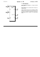
System A - 100 doepfer VC Phaser A-125 1. Introduction Level Audio In A-125 VCP CV 2 Module A-125 (VC Phaser) is a voltage controlled phase shifter. Phase shifting can be controlled either manually or by voltage control. Shift CV CV Other parameters which can be controlled are resonance (governing the depth of the comb filtering, and tonal color - see page 3) and mix (the amount of the original signal which is added to the phase-shifted signal).
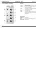
A-125 VC Phaser System A - 100 Controls: 2. VC Phaser - Overview A-125 VCP VC PHASE SHIFTER Audio In Level 0 0 ➀ 10 Shift ➁ 1 Level : Attenuator to control the level of the signal at input ! 2 Shift : Control for manually setting the amount of phase shift 3 CV : Attenuator for the phase shift voltage control signal at input " 4 Res. : Resonance control 5 Mix : Control for setting the amount of the original signal added to the phaseshifted signal 10 CV CV 0 ➂ In / Outputs: 10 Res.
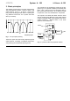
System A - 100 doepfer 3. Basic principles The phasing process relies on dynamic comb filtering. The comb filtering produces a series of gaps in the audio spectrum (in Fig. 1, at 200 Hz, 1 kHz and 5 kHz), by the cancelling process which is created byhaving identical sounds 180° out of phase with each other (or ‘inverted’). VC Phaser A-125 The principle can be explained by looking at the diagram (Fig. 2) of a phaser created by three band pass filters.
A-125 VC Phaser System A - 100 4. Controls 1 Level Attenuator 1 controls the level of the input signal. 2 Shift Phase shift amount is controlled with this knob, in a range from around 0° to 180°. 3 CV As well as manual phase shifting, a control voltage at input " can modulate the shift. Attenuator 3 sets the level of voltage control. As a rule, a slowly changing signal (eg LFO, ADSR, Random, etc.) is used for this modulation. 4 Res.
doepfer System A - 100 VC Phaser A-125 5. In / Outputs 6. User examples ! Audio In Standard set-up Socket ! is the phaser’s audio input. Fig. 3 shows a typical patch, with various alternative sources of slow-changing modulators affecting the speed of the phase sweep. " CV The control voltage for modulating the speed of phase shifting is input at socket ". You can set the level of this CV with control 3.
A-125 VC Phaser System A - 100 The phaser is simply inserted in the audio path like this. For modulation sources, you could use, for instance, any of the following: Alternative Module 1 LFO A-145 2 ADSR slow envelope A-140 3 Effect low frequency (< 2 Hz) free-running phase-shift Random slow random A-118 rate keyboardcontrolled phaser random phasing 4 S&H A-148 random phasing 5 A-190 any MIDI conCV 2 troller for CV 2 (eg.
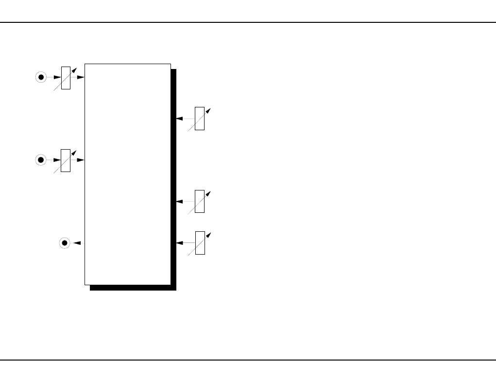
doepfer System A - 100 VC Phaser A-125 7. Patch-Sheet The following diagrams of the module can help you recall your own Patches. They’re designed so that a complete 19” rack of modules will fit onto an A4 sheet of paper. Photocopy this page, and cut out the pictures of this and your other modules. You can then stick them onto another piece of paper, and create a diagram of your own system.
A-125 VC Phaser 8 System A - 100 doepfer