
User Manual

doepfer
System A - 100
Headphone Amplifier
A-139
3
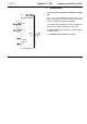
3. Controls
1 Lev. 1 • 2 Lev. 2
Attenuators 1 and 2 adjust the relative level of the
audio signals at inputs
!
and
"
respectively. Basi-
cally, these controls are used to compensate for diffe-
rent levels of the input signals.
3
Master Level
Control
3
is used to adjust the overall loudness and
affects both channels (stereo potentiometer).
Important:
Turn this knob fully counterclockwise and
then turn it slowly clockwise until the desired loudness
is reached.
Extreme audio levels will damage your
hearing !
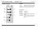
4. In- / Outputs
! Input 1 • " Input 2
Audio inputs ! and " are connected to the audio
sources to be amplified (e.g. final VCA outputs).
§ Head Phone • $ Head Phone
Jack sockets
§
and
$
(internally connected) are the
headphone outputs of the module.
Connect one or two
stereo headphones
with
1/4”
stereo jack plugs and minimum 8 Ohm impedance
to these outputs.
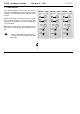
H
Monting of the A-139 module
Module A-139 uses integrated amplifier circuits with
high fixed gain. The result is that the module is very
sensitive to earth hum resulting from ground loops
(bus board - patch cords - front panels - frame - mains
GND).
Therefore isolating spacers and plastic washers are
enclosed with the module. These enable isolated
installation of the module into the A-100 frame, i.e. with
no electrical connection between the front panel and
the frame via the mounting screws.
In case your A-139 module generates an unacceptable
amount of earth hum, these washers and spacers
should be used for mounting the module within the
frame.