
User Manual


A-140
ADSR
System A - 100
doepfer
4
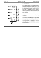
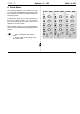
5 ADSR Control
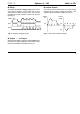
LED 5 gives a visual indication of the envelope voltage
at the output.
6 Time Range
This 3-position rotary switch lets you select the right
time range for your requirements. The three positions
are:
•
H (high): up to minutes
• M (medium): standard mid-range
• L
(low): down to less than 100 µsec
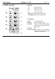
4. In / Outputs
! Gate
Socket ! is the ADSR’s gate input.
H The gate input is a switched socket, normalled
to the
INT. GATE circuit
on the
system bus
. A
gate signal on this circuit (for instance from a
keyboard) will trigger the ADSR, even without
an input to socket
!
.
If on the other hand you connect a gate signal to
socket
!
,
then the connection with the system bus is
broken, and the ADSR is triggered from this socket
instead.
If you want, you can undo the normalling to the system
bus more permanently, by turning the A-100 off, remo-
ving the A-140 module, and taking out the little red
jumper in the top right-hand corner of the circuit
board.