
User Manual


doepfer
System A - 100
ADSR A-140
7
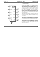
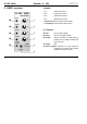
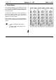
6. Patch-Sheet
The following diagrams of the module can help
you recall your own Patches. They’re designed so
that a complete 19” rack of modules will fit onto an
A4 sheet of paper.
Photocopy this page, and cut out the pictures of
this and your other modules. You can then stick
them onto another piece of paper, and create a
diagram of your own system.
Make multiple copies of your composite diagram,
and use them for remembering good patches and
set-ups.
P • Draw in patchleads with colored
pens.
• Draw or write control settings in the
little white circles.
A-140
ADSR
Retrig.
Output
Inverse
Output
ADSR
Control
Gate
Output
0
10
H
L
M
Time
Range
A
D
S
R
0
10
0
10
0
10
A-140
ADSR
Retrig.
Output
Inverse
Output
ADSR
Control
Gate
Output
0
10
H
L
M
Time
Range
A
D
S
R
0
10
0
10
0
10
A-140
ADSR
Retrig.
Output
Inverse
Output
ADSR
Control
Gate
Output
0
10
H
L
M
Time
Range
A
D
S
R
0
10
0
10
0
10