
User Manual

doepfer
System A - 100
Clock Sequencer A-161
1
1. Introduction
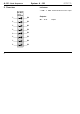
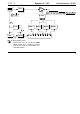
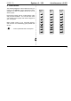
Module A-161 is an eight-step Clock Sequencer
which is internally connected to the Clock Divider
(A-160)
.
Eight outputs
are sequentially switched by
the clock signals from the A-160 (see Fig. 1) and can
act, for instance, as sequential rhythmic triggers for an
envelope. The reset on the A-160 also works on the
A-161 (instant return to Step 1).
A
Installation in the rack system:
The A-161 must be positioned
directly to the
right of the A-160.
Join the two modules with the supplied 10-way ribbon
cable. Use the
upper
10-way socket on each module.
Make sure that the ribbon cable isn’t twisted, and that
the colour-coded section is oriented the same on both
modules.
Only join the
A-160
to the
system bus
! Leave the
lower 10-way socket on the A-161 unused.
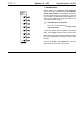
A-161
1
2
3
4
5
6
7
8
Clock
Sequencer