DOEPFER Analog Synthesizer Kit DIY SYNTH User's Guide © 2010 by Doepfer Musikelektronik GmbH Geigerstr. 13 82166 Graefelfing Deutschland / Germany Phone: + 49 89 89809510 Fax: + 49 89 89809511 Web Site: www.doepfer.com Email: sales@doepfer.
Important note The DIY Synth kit is planned for experienced users only who are familiar with both electronics and analog synthesizers. It is definitely unsuitable for beginners ! For example we will not be able to offer the service to repair a customers assembly if it does not work as it should, or to make individual suggestions how to wire the board for special applications.
Warranty • All connections have to be carried out in the off-state of the DIY Synth kit (i.e. without power supply) • The DIY Synth kit is an electrostatic sensitive device. Avoid any electrostatic charges ! • Do not solder directly to any of the pin headers but use connectors to make the connections between the DIY Synth kit and your application. • Use only a power supply that corresponds to the specifications given in this manual (i.e. +12V/GND/-12V).
Table of contents Important note ..........................................................................................................................2 Electrical safety / EMC compatibility ........................................................................................2 Warranty...................................................................................................................................3 Table of contents.....................................................................
Introduction The DIY synth kit is a low cost DIY kit to build a full-fledged analog synthesizer.
The kit is planned for customers who are familiar with electronic basics as the kit does not include the controls, switches, sockets, power supply and the case. These elements have to be added and wired by the. The customer can choose the desired size, shape, type and color of these elements (e.g. rotary potentiometers or faders, small 3.5 mm jack sockets or ¼" sockets or banana type, small or large knobs and switches and so on).
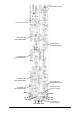
DIY Synthesizer kit (pc board schematics) User's Guide page 7 DIY Synth Kit
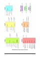
Connecting controls and sockets Please refer to the picture on the next page. Remarks for all connectors: • Each of the pin headers JP1...
P2 VCO frequency offset P2 VCO frequency scale pin header JP2 (see detailed table) pin header JP7 (see detailed table) pin header JP3 (see detailed table) pin header JP4 (see detailed table) pin header JP6 (see detailed table) pin header JP10 (Tempco option) pin header JP5 (see detailed table) GND GND -5V -12V -12V GND +12V User's Guide page 9 +5V +12V pin header JP1 (power supply) DIY Synth Kit
JP1: Power Supply A stabilized, symmetrical power supply with +12V, GND and –12V and a minimum of 150 mA (for both voltages +12V and –12V) is required. A high quality, stabilized supply is recommended as the power supply affects the stability of the modules (especially the VCO). For example the power supplies of the A-100 modular system can be used (e.g. the miniature power supply A-100MNT with ±12V/200mA).
JP2: VCO and VCF connections JP2 contains some VCO and VCF terminals.
JP3: VCF, VCA and LFO connections JP3 contains some VCF, VCA and LFO terminals.
JP4: LFO and ADSR connections JP4 contains some LFO and ADSR terminals.
Remark: Several gate signals can be combined via diodes and connected to the gate input. Another possibility is to connect the switching contact of the gate socket to the rectangle output of the LFO. In this case the ADSR is triggered automatically by the LFO unless another gate signal is connected to the gate socket. JP5: LFO and ADSR connections JP5 contains some ADSR, Buffer and Inverter/Mixer terminals.
JP6: LFO, ADSR and Slew Limiter connections JP6 contains some ADSR, LFO and Slew limiter terminals. pin header top view Function LFO LED GND ADSR SW SLOW ADSR SW COMM ADSR SW MEDIUM GND GND GND SLEW IN SLEW OUT ribbon cable Explanation LFO LED display Remark / Recommendation Usually connected to a dual color LED. The second terminal of the LED is connected to GND (e.g. the following wire). e.g.
JP7: VCO, VCF and VCA connections JP7 contains some VCO, VCF and VCA terminals.
VCF CV SUM Control voltage summing input for VCF frequency VCA OUT VCA Output Required only if the two VCF CV inputs of JP3 are not sufficient, serial resistor 100k required to obtain roughly 1V/octave (or ~ 47k for 0.5V/octave) Usually connected to a socket labelled "VCA Out", which is normally the final output of the synthesizer and connected to the audio mixer JP10: Tempco-Option If the tempco option is used IC1 has to be removed and replaced by the tempco option.
Application Example These symbols for electronic parts are used in the following: Resistor equivalent US symbol Potentiometer equivalent US symbol Socket (any type, e.g. 3.5 mm miniature jack socket, 1/4" jack socket, banana socket Socket with switching contact for signal normalling Toggle switch 1-0-1 with center position Diode or LED GND connection Positive voltage terminal (e.g. +12V or +5V) Negative voltage terminal (e.g.
User's Guide page 19 DIY Synth Kit
How to use the summing inputs Each voltage controlled parameter (e.g. VCO frequency or VCF frequency) has at least one control voltage (CV) input available. If the number of CV inputs is not sufficient more inputs can be added. For this we have to take a look at the input circuit used for all types of control voltage summing applications.
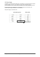
Attenuating signals In many applications it is necessary to attenuate a signal (e.g. to adjust the ADSR modulation amount of the VCF or the audio signal input of the VCF). The following simple circuit is recommend to attenuate a signal: Uin Uout At the output of this circuit (Uout) appears the attenuated input signal (Uin). A typical value for the potentiometer is 50…100k. Depending upon the application a linear or logarithmic potentiometer type can be used.
Application idea: In each circuit a variable resistor can replaced by an LDR (light depending resistor). For an LDR the resistance value depends upon the illumination and ranges from some MOhm (dark state) to some hundred Ohm (bright illuminated state). For example the decay or slew time can be controlled by an LDR that is shadowed by the hand (instead of or additional to the usual manual control).
Controlling the LFO frequency The LFO frequency is controlled by a potentiometer connected to the terminals LFO POT CCW, LFO POT CENT and LFO POT CW of JP3: LFO POT CW CW 100k … 1M log LFO POT CENT CCW LFO POT CCW Another type of LFO control is the usage of separate controls for the rising and falling slope. In this case the wiring of the LFO pins is a bit different: LFO POT CENT LFO POT CW 2 x 1...5M log In this case the terminal LFO POT CCW is unused.
Doepfer Musikelektronik www.doepfer.