MTC64 (Midi To Gate/Contact Converter) User’s Guide Version 2 © 2012 by Doepfer Musikelektronik GmbH
Electrical safety / EMC compatibility MTC64 is a so-called OEM product (OEM original equipment manufacturer) that cannot be used independently but has to be combined with additional electrical or electronical equipment to become a working device (e.g. relays, LEDs, lamps, magnets, magnetic valves, power supply, case/housing). The manufacturer of MTC64 does not know the final assembly of the complete device in which the MTC64 is used as a part of the complete device.
Contents Electrical safety / EMC compatibility ........................................................................................2 Warranty...................................................................................................................................2 Contents ...................................................................................................................................3 Introduction................................................................................
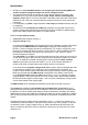
Introduction • • • • MTC64 is an universal MIDI interface that converts up to 64 succeeding MIDI note on/off or program change messages into 64 TTL voltages (0/+5V). The outputs of the MTC64 can be used to control different switching functions. With suitable drivers (e.g. switching transistors) relays, lamps, motors, electromagnets, magnetic valves and so on can be controlled.
MTC64 is equipped with MIDI In and Thru. The incoming MIDI messages are passed to MIDI Thru. In this way several MTC64 can be linked together. MTC64 is available only as an assembled and tested pc board (about 70 x 105 mm). Three mounting holes for mounting the pc board to a suitable base are available. We do not offer a suitable housing as the MTC64 is normally installed into the housing of the device to be controlled by MTC64. An external power supply (7-12V @ min. 100mA) is required.
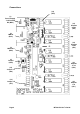
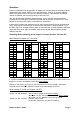
Connections (14) (JP5) (1) Power Supply 7-12V/100mA DC (BU3) (10) Outputs 49-64 (JP4) (2) MIDI In (BU1) (10) Outputs 33-48 (JP3) (3) MIDI Thru (BU2) (4) Control (LED) (12) Jumper 1-8 (JP6) (13) Jumper 1-5 (JP7) Page 6 1 2 3 4 5 6 7 8 (10) Outputs 17-32 (JP2) 1 2 3 4 5 (10) Outputs 1-16 (JP1) MTC64 V2 User’s Guide
(1) Power Supply (BU3) The MTC64 does not have a built-in power supply. Instead it uses a plug-in type external power supply (AC adapter). One reason for this feature is electrical safety. Keeping danger voltages (main) out of the MTC64 increases the electrical safety. Therefore an external power supply of high quality and safety should be used. If the keyboard is used in Germany the external power supply has to be VDE approved.
Additionally there are some GND pins available (JP8, JP9, JP10) between the double row pin headers. GND is also available at JP5 (see below). Remark: The GND reference level is required for connecting the devices controlled by the MTC64 outputs. (12) Pin Header JP6 / Jumper 1...8 The MTC64 configuration (MIDI channel, operation mode, offset) is adjusted with the 8 jumpers of the double row pin header JP6: • • • • The jumpers 1...4 of JP6 are used to define the MIDI channel.
Operation MTC64 is switched ON by plugging the AC adapter into a wall outlet and connecting it to the appropriate power supply socket (1) on the MTC64 board. There is no separate ON/OFF switch. After power on the LED (4) on the MTC64 will light up. Otherwise the AC adapter used is not suitable, has the wrong polarity or does not work. After this all MIDI data appearing at the MIDI input (2) are scanned and checked if they correspond to the settings of the MTC64 specified with the jumpers of JP6 and JP7.
Note/program basic offset (Jumper 8 of JP6) Jumper 8 installed: Jumper 8 removed: offset = 0 (factory setting) offset = 36 (in note/control change mode) offset = 64 (in program mode) Remark: If you want to change the note/control change offset (= note number or control change number assigned to output #1) to the standard note number 36 (= lowest "C" of a standard 5 octave MIDI keyboard) jumper 8 has to be removed ! This applies probably in most cases when note mode is chosen.
Check list In case that your MTC64 installation does not work at the first go please check the following points: • Is the power supply working correctly ? After power on the LED has to be on ! Otherwise the AC adapter used is not suitable, has the wrong polarity or does not work. The correct polarity is: outside ring = GND, inside lead = +7...12V.
Appendix Connection schematics of the MTC64 64 | | | | | | 49 48 | | | | | | 33 32 | | | | | | 17 16 | | | | | | 1 16 pin double row female socket connectors with 16 pin flat cable Page 12 0/+5V outputs MTC64 V2 User’s Guide
Basic Test The basic function of MTC64 can be tested very easily: • Connect a low current LED (max. 2 mA) via a current limiting resistor (about 2 kOhm) between output #1 and GND. • Select the inverse polarity (JP7 / Jumper 5 installed) • Connect the power supply • The LED will light up if everything is OK. • If now the MIDI message that activates output #1 (i.e. note on or program change message) is sent to MIDI In of the MTC64 the LED will turn off. Otherwise you have not chosen the correct settings (i.e.
Output Driver Circuit The MTC64 outputs are able to drive only about max. 5 mA in the "high" state (+5V) and about max. 10 mA in the "low" state (0V). If one wants to drive higher loads (e.g. lamps, relays, electromagnets, electromagnetic valves or similiar) an additional driver for each MTC64 output is required. Each MTC64 output is connected to the base of a power transistor (e.g. BD135) via a resistor (about 10 kOhm). The emitter of the transistor is connected to GND. The load (i.e.
CTM64 The counterpart to MTC64 is the Contact To MIDI interface CTM64 that converts up to 64 free contacts into 64 succeeding note or program change messages. Closing a contact connected to the CTM64 causes the transmission of the corresponding MIDI note or program change message. CTM64 can be used to retrofit keyboards, switches, button arrangements or any other types of contactes with MIDI out.
Doepfer Musikelektronik www.doepfer.