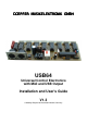
DOEPFER MUSIKELEKTRONIK GMBH USB64 Universal Control Electronics with Midi and USB Output Installation and User's Guide V1.
Table of contents Table of contents.................................................................................................................................... 2 Electrical safety / EMC compatibility ....................................................................................................... 3 Warranty ................................................................................................................................................ 4 Introduction .............................
Electrical safety / EMC compatibility USB64 is a so-called OEM product (OEM original equipment manufacturer) that cannot be used independently but has to be combined with additional electrical or electronical equipment to become a working device (e.g. potentiometers, switches, power supply, case/housing). The manufacturer of USB64 does not know the final assembly of the complete device in which the USB64 is used as a part of the complete device.
Warranty • • • • • • • • • • • Applying any negative voltage (< 0V) or positive voltage above +5V (> +5V) to one of the 64 analog inputs (JP1 – JP8 ) will destroy the circuit ! If potentiometers and/or switches are connected between GND and +5V of USB64 as described in this manual no problems will occur.
Introduction • • • • • • • • • • • • • USB64 is an universal electronics DIY kit to built your own Midi control box. Up to 64 controls can be connected to USB64 transmitting Midi Control Change or note on/off or program change messages. Typical examples for controls that can be used are rotary potentiometers, fader/slider potentiometers, momentary switches, toggle switches, foot switches or foot controllers. The controls are not included but have to be added by the customer.
Connection and Installation Please pay attention to the following notes ! Electronic basic knowledge is required to install the USB64 electronics and to connect the controls resp. control voltages. If you are not sure whether your knowledge is sufficient please consult an expert. We cannot take back modules that became defective because of wrong installation or wrong connection of the controls or voltages. We also cannot take back modules or cables which have been soldered by the user.
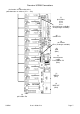
Overview: USB64 Connections (5) pin headers for connection of the potentiometers or switches (JP1 ... JP8) (7) pin headers JP10 JP14 JP11 JP12 (no longer available) JP15(no longer available) (9) control LED (8) pin header JP13 (no longer available) (4) USB (BU4) (3) external power supply 7-12V/100mA DC (BU3) (1) MIDI IN (BU1) (2) MIDI OUT (BU2) (6) pin header JP9 USB64 User's Guide V1.
USB connector (4) If the data generated by USB64 has to be transmitted via USB the socket (4) is connected to the USB socket of the receiver (normally that's a computer with USB interface). The operating system of the computer has to support the so-called generic USB device class driver for Midi devices. This driver is supported by Windows XP (SP2 recommended), Vista and Mac OSX operating systems. Consequently older Windows or Mac operating systems that do not include this driver cannot be used.
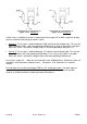
The right part of the sketch shows the pin out of the pin headers. Normally 10 pin female connectors with ribbon cables are plugged to the pin headers JP1 – JP8. Eight female connectors with ribbon cables are included with the USB64. The controls (e.g. potentiometers or switches) are soldered to the open ends of the ribbon cable. The left part of the sketch shows the pinout of the 10 wires of the ribbon cables.
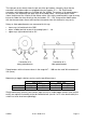
Connection of a momentary or toggle switch (version 1) Connection of a momentary or toggle switch (version 2) In both cases an additional resistor is required (possible range 4k7 to 100k) to pull the analog input to a defined state during the switch is open. • Version 1: The resistor is soldered between GND and the control voltage input. This way the input is pulled to GND ( =0V corresponding to Midi data 0) as long as the switch is left open.
Configuration of the USB64 The configuration of the USB64 is carried out by several jumpers that have to be put on pin headers. Configuration means in this context the adjustment of the parameters that define the behaviour of USB64: e.g. Midi channel, type of Midi event, controller/note/program number assigned to the first input, supply via external power supply or USB, USB active/inactive and so on.
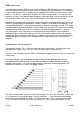
The following table shows the relation between the settings of the jumpers 5…8 of JP1 and the corresponding preset: Preset # 1 2 3 4 5 6 7 8 9 10 11 12 13 14 15 16 5 ■ ■ ■ Jumper # 6 7 ■ ■ ■ ■ ■ ■ ■ ■ ■ ■ ■ ■ ■ ■ ■ ■ ■ ■ ■ ■ Configuration / Preset description 8 ■ ■ ■ ■ ■ ■ ■ ■ control change 0 – 63 (analog) note 0 - 63 (digital) programm change 0-63 (digital) polyphonic aftertouch 0-63 (analog) control change 0 – 31, note 0-31 (analog/digital mixed ) control change 32 – 63, note 32-63 (analog/digi
• • • • • As the scanning of the 64 inputs is analog even in this mode (i.e. analog-to-digital conversion) the scanning is not as fast as e.g. for a Midi keyboard. It is planned to control functions that are triggered by Midi note messages (e.g. for Ableton Live) but not as a Midi keyboard. For Midi keyboard applications the scanning is not fast enough. We recommend the OEM/DIY electronics CTM64 for this application. Preset #3 generates Midi programm change messages in the range 0 – 63.
Normal operating mode: This is the usual working mode. In this mode the LED flashes for about 2 seconds after power on and then stays lit. As soon as Midi messages are generated by the USB64 the LED flashes to indicate the Midi out activity of USB64. Consequently the LED can be used to check the fundamental function of USB64. Update Mode: The update mode is used to update the firmware of the USB64.
(8) Pin header JP13 JP13 was used to choose the type of power supply. If an external power supply was used to run the USB64 the jumper had to be in the lower position (towards the voltage regulator 7805). If USB64 was powered via USB the jumper had to be in the upper position (towards the LED) and the external power supply had to be removed. This was the situation till version V1.2. Now in V1.3 this is made automatic by two diodes BAT42, which are assembled instead of JP13 and the jumpers.
Mounting Before USB64 is put into operation the board has to be fixed on a suitable support and built into a metal case together with the controls (refer to EMC notes on page 3). The metal case has to be connected to GND of USB64. We recommend to use the metal plate of the voltage regulator 7805/IC12 or the GND terminal of the power supply socket for this connection. The board measures about 159 x 53 x 25 mm. Four mounting holes with 3 mm diameter are available for mounting the board inside the case e.g.
Dimensions Dimensions USB64 USB64 User's Guide V1.
Check list In case that your USB64 installation does not work at the first go please check the following items: • Does the power supply work correctly ? • Does the LED behave after power on as described ? • Pay attention to the correct setting of JP13 for the desired power supply type, if you did not use the automatic power selection with the diodes assembled instead of JP13 ! • Are the controls connected correctly as described in this manual ? • Was no short circuit made (neither in the wiring nor mounting
Extent of delivery The USB64 delivery contains the following parts: • • • • • • USB64 pc board, assembled and tested Power Supply (230V mains voltage, European type mains plug, output voltage range 7...12V, current min. 100 mA) included only for shipments within Germany, for shipments outside Germany please contact your local representative or dealer This USB64 user's guide Eight 10 pin ribbon cables with double row female connectors, cable length about 30 cm each USB cable, type A – B 64 resistors 4k7...
Doepfer Musikelektronik www.doepfer.com Doepfer Musikelektronik GmbH Geigerstr. 13 D-82166 Graefelfing / Germany Phone 49 89 89809510 Fax 49 89 89809511 Email: sales@doepfer.