
User Manual


FIBER OPTIC LIGHT PIPE INSERTION
Insert the Fiber Optic Light Pipe into the adapter and tighten the thumbscrew to secure
the fiber optic in the Illuminator.
MOUNTING STANDS
For some applications a mounting stand is required to secure the fiber optic gooseneck
in an operating position. The EEG 3736 fiber optic has a hole in the transition to accept
the securing knob on the MS-7 Mounting stand. The MS-8 Mounting stand requires that a
portion of the gooseneck be clamped directly.
LENSES
The LH755 lens is threaded on the fiber optic light pipe after the locking nut. The
LH759 lens is quickly attached or removed from the fiber optic with a turn of the
thumbscrew. Both lenses are capable of focusing the light to provide higher levels of
illumination and obtaining focused light spot diameters of .16" (.4cm) to 2.87" (7.3cm).
ANNULAR ILLUMINATION SYSTEMS
Annular Illumination Systems provide 360 degrees oblique crosslighting for detail
delineation and a crisp visual or photographic image at working distances of 1.5" (3.8
cm) to 9.5" (24.1 cm). As is the case with most non-self-supporting fiber optics and
especially with this system, a capability for electronic flash photography is acquired by
simply approximating the fiber optic to the flash source. This system has numerous
adapters for attaching the fiber optic to various models and makes of microscopes. These
adapters necessarily vary and a separate instruction sheet is provided for each.
A WORD ABOUT FIBER OPTIC LIGHT PIPES
The light pipe contains a bundle of individual glass fibers about the size of a human
hair. Each fiber consists of a central optical glass core and is cladded with a different
refractive index which allows for the transmission of light through total internal
reflection, a phenomenon in which light rays are reflected at the core/clad interface and
travel to the distant end of the fiber by a zigzag path of successive reflections. To assure
maximum light input/output each fiber bundle has an optical polish at each termination.
These bundles are then constructed in a protective sheathing to limit a bend radius
which, if exceeded, could cause the fibers to fracture. The fiber optic light pipe should be
treated as a laboratory instrument and considerate, common sense usage will assure an
unlimited lifetime. Avoid sudden forceful pressures on bends and excessive
configurations that strain the flexibility of the fiber optic.
Periodically the ends of the fiber optic and lenses should be cleaned with a lens cleaner
and lens paper.
1
2
3
4
5 6
7
8
9
10
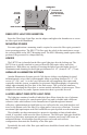
INTENSITY
ON
OFF
THUMBSCREW
NOSEPIECE
INSERT ADAPTER
FLAT with
IDLER HOLE
CHANGING THE ILLUMINATOR LAMP
Should the need arise to replace the EKE type lamp the following procedure should be
used:
1. Unplug the illuminator from the wall socket.
2. Wait until the illuminator nosepiece is cool to touch.
3. Raise the cover of the illuminator.
4. Pull up on the EKE lamp to remove it from the lamp holder.
5. Remove the lamp from the socket.
6. Replace with a new EKE lamp.
CAUTION: Do not touch either the inner quartz lamp envelope or the lamp pins with
your fingers. This will result in a significant shortening of lamp life. Handle the EKE
lamp only by the dichroic reflector when attaching the lamp socket.
7. Reinsert the lamp holder.
8. Close cover.
9. Insert plug in wall socket and, if necessary, check the alignment of the lamp.
10. The lamp holder is precision aligned at the factory on the angle for optimum lamp
input into the fiber optic. Occasionally there are dimensional variations of replacement
lamps that may result in a reduction of illumination. The reduction is apparent when
illuminating a piece of white paper at a distance of three inches with an unlensed fiber
optic. Should there be visible a central area of less intensity than the periphery, the lamp
should be aligned. This condition is due to the physical positioning of the quartz
envelope within the reflector and can be eliminated by the following:
ALIGNMENT:
1. Illuminate a piece of paper with the distal end of the fiber optic about 3" away. Do not
use a lens. Check for a darker central area.
2. Place the illuminator on its side and loosen the two lamp holder adjustment screws on
the base. With the screws loose, rotate the lamp holder until the darker central area
changes to a brighter intensity than the periphery.
3. Secure the screws at the best position obtainable.
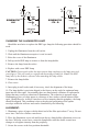
FAN MOTOR
BK
XFMR
W
W
LAMP
BK
BK BK
W
R
LINE
SCHEMATIC
180
G
(For system 181,
181A and 181B see
System 181 Assembly
instructions.)
FAN MOTOR
BK
XFMR
W
W
LAMP
BK
BK BK
W
R
LINE
G
SCHEMATIC
170 - D