430 SERIES BACKGROUND NOISE SUPPRESSOR SYSTEM Installation and Operating Instructions MAIN
INSTALLATION AND OPERATING INSTRUCTIONS FOR 430 SERIES BACKGROUND NOISE SUPPRESSOR SYSTEM Dolby Laboratories Incorporated U.S.A. 100 Potrero Avenue, San Francisco, CA 94103 Tel: 415-558-0200; Fax: 415-863-1373 U.K.
DOLBY 430 BACKGROUND NOISE SUPPRESSOR DOLBY 430 BACKGROUND NOISE SUPRESSOR he Dolby 430 Series is a background noise suppressor system for reducing the broadband noises such as wind or traffic rumble that often mar location recordings. Many mixers in film and television postproduction already rely on Dolby Laboratories’ Cat. No. 43, a background noise suppression unit based on a modified version of Dolby A-type noise reduction.
30 SPECIFICATIONS DOLBY NOISE REDUCTION Dolby noise reduction is a family of signal processes that reduce the noise inherent in analog recording media, without affecting the sound being recorded. While they differ in performance and details of operation, all Dolby NR systems are complementary processes that first encode the music when it is recorded, then decode it when it is played back.
i TABLE OF CONTENTS INTRODUCTION SECTION 1 UNIT CONFIGURATIONS 1.1 1.2 The Model 430 System .................................................................................................. 1-1 Accessories .................................................................................................................... 1-1 SECTION 2 OPERATION 2.1 2.2 2.3 Controls ..........................................................................................................................
ii INTRODUCTION The Model 430 Series is a playback-only noise reduction system intended primarily to reduce unwanted ambient noise from location recordings. Typically, this noise is generated by broadband sources such as generators, wind, or traffic. The Model 430 Series is a second-generation design, following from the Cat. No. 43 unit—a successful background noise suppressor in widespread use in post-production facilities throughout the world.
1-1 SECTION 1 UNIT CONFIGURATIONS 1.1 The Model 430 System The Model 430 is a modular system which has a control unit containing the power supply and microprocessor. The control unit links to one or more enclosures each of which contains one or two noise suppression modules and also links to one or more remote control modules. The 40mm wide format of the remote control modules makes them easily mountable in spare sections of many mixing consoles.
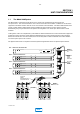
1-2 1.2 Accessories The figure below shows the various 430 Series accessories available. These items can be ordered to expand an existing system. 430SK1 1 CHANNEL SUPPRESSOR KIT Clip CAT. NO. 429 REMOTE CONTROL Pull to Adjust Level CAT. NO. 413 NOISE SUPPRESSOR BOARD 0 1 Dolby Cat. No. 413 430 Series Noise Suppressor Module Normal Bypass 2 3 4 5 LF HF Dolby 430 Series Remote in Clip Clip Pull to Pull to Adjust Adjust Level Level 430SU2 2 CHANNEL SUPPRESSOR UNIT CAT. NO.
2-1 SECTION 2 OPERATION 2.1 CONTROLS Operation of the Model 430 is very simple. The basic controls and indicators mounted on the Cat. No. 429 remote for each channel are described below. 3 Clip Pull to Adjust 4 2 Level 0 1 2 3 4 5 LF HF Dolby 430 Series Remote in 1 A1F4356F 1 In/Out Switch and Indicator This push-button switches all processing in and out so that the effect can be checked against the original track. An LED indicator on the remote unit confirms switch action.
2-2 4 High-frequency and Low-frequency Suppression Controls The left-hand slider controls the amount of low level LF attenuation the unit applies; the right-hand slider controls the low level HF attenuation. When the controls are at the top there is no processing, and at the bottom there is maximum processing. The effect is gradual with about half scale giving enough processing for most applications; only on severely noisy tracks will more than half scale be needed.
2-3 It is usually better to locate the console channel fader after the Model 430 unit. Gain riding the Model 430 input can allow dialog to move into the expansion band resulting in unexpectedly increased dynamic range. Also, when the Model 430 is being used to reduce reverberation the process can change the perceived loudness of the track (even though levels around nominal are virtually untouched).
3-1 SECTION 3 INSTALLATION 3.1 Control unit and Suppressor Frames The installation of Model 430 series consists of plugging together the component parts and rack mounting (prefereably) the control unit and each two-channel frame. Taking a typical system with three channels, the procedure is as follows: The system should be unpacked and inspected for damage. Any damage should be reported to the carrier and distributor immediately.
3-2 Similarly there is a slot in the back of each two-channel frame and the other connectors should be mated, (bump upwards) with these observing the warning about excessive force. The channel frames can be stacked with the control unit at the top or bottom. Next, the 15 meter shielded cable should be located and plugged into the 15-way D connector on the back of the control unit. The other end of this cable connects directly to the rear of an optional Cat. No.
3-3 3.2 Console Mounting of Remotes. If optional Cat. No. 428 remote housings (holding up to three remote control units each) are not used, the remote controls can be placed in spare sections of the console. The size of each remote unit is 150 mm x 39 mm with a maximum projection behind the control surface of 100 mm. The shielded cable connecting them to the main control unit can run in any convenient trunking to the console although trunking which carries high level signals is preferred.
3-4 3.4 Panel Cut-Out Templates for Cat. No. 428 Remotes The templates below can be removed from this manual and used to cut/drill blank console panels.
3-5 3.5 Regulatory Notices WARNING: Check that the unit has been set to the correct supply voltage and that the correct fuse is installed. To reduce the risk of fire, replace the fuse only with the same type and rating. For 100/120 Vac, use 1.25A/250 V 1/4" x 1-1/4" slow-blow fuse. For 220/240 Vac, use T630 mA/250 V 5 x 20mm time-lag fuse. The power supply input connector has positions for two fuses and will accept carriers for either 20 mm or 1.
3-6 IEC NOTICES IMPORTANT SAFETY NOTICE This unit complies with the safety standard IEC65. To ensure safe operation and to guard against potential shock hazard or risk of fire, the following must be observed: • Ensure the voltage selector is set to the correct mains voltage for your supply. • Ensure fuses fitted are the correct rating and type as marked on the unit. • The unit must be earthed by connecting to a correctly wired and earthed power outlet.
4-1 SECTION 4 THEORY OF OPERATION Based on the Dolby SR spectral recording system, the Model 430 series design incorporates two separate noise reducing bands; one for low and the other for high frequencies. Unlike SR, however, the degree to which the signal is treated can be controlled by two slider controls and the level at which the expanders work is adjustable by a rotary control which has a nominal “cal” position.
4-2 In situations where the interference is broadband, both the LF and HF bands can be used in varying amounts. The two expander sections are in series therefore their effects tend to sum. For this reason, it will be found that the amount of processing used can often be reduced when both bands are brought into play since they broadly overlap in the band 200 Hz to 2 kHz.
5-1 SECTION 5 SCHEMATIC DIAGRAMS- Contact Dolby Laboratories Figure 5-1 Figure 5-2 Figure 5-3 Figure 5-4 Figure 5-5 Figure 5-6 Power Supply ......................................................................................................................... 5-2 Control Circuit ........................................................................................................................ 5-3 Cat. No. 413 Voltage Regulation/Smoothing ............................................................
A-1 APPENDIX A1 Plugging Precautions Any Cat. No. 413 suppressor module can be removed and replaced with the power applied. However it will only take on the settings determined by its remote contol unit after every control on the remote has been exercised. Similarly, the remote controls can be plugged and unplugged with the power on although it has been found that the normal bypass indicator can occasionally get out of sync with the front panel LEDs if the reconnection is not made smoothly.