Model DP503 Two Channel AC-2/AC-3/MPEG Digital Audio Encoder and Dolby Fax System Users' Manual MAIN
MAIN
Users' Manual For Model DP503 Two Channel AC-2/AC-3/MPEG Digital Audio Encoder and Dolby Fax System Dolby Laboratories Incorporated U.S.A. 100 Potrero Avenue, San Francisco, CA 94103 Tel: 415-558-0200; Fax: 415-863-1373 www.dolby.com U.K.
MAIN
TABLE OF CONTENTS SECTION 1 INTRODUCTION 1.1 Introduction ...............................................................................................1-1 1.2 Features......................................................................................................1-2 1.3 Dolby AC-2 and Dolby Digital (AC-3) .....................................................1-2 1.4 Available Algorithms, Data Rates and Sample Rates ...............................1-3 1.5 Regulatory Notices ...........................
ii SECTION 4 INSTALLATION and LEVEL CALIBRATION 4.1 Mounting ...................................................................................................4-1 4.2 Audio Connections....................................................................................4-1 4.2.1 S/PDIF Input............................................................................4-1 4.2.2 AES/EBU Input.......................................................................4-1 4.2.3 Analog Input............................
iii 5.4 5.5 Using the DIRectory: Dolby Fax Applications..........................................5-13 5.4.1 Entering DIRectory Mode .......................................................5-13 5.4.2 Creating New Directory Entries ..............................................5-14 5.4.2.1 Using the COPY ENTRY? Feature.............................5-18 5.4.3 Using Directory Entries ...........................................................5-19 5.4.4 Editing Directory Entries.................................
MAIN
SECTION 1 INTRODUCTION 1.1 Introduction The Dolby Model DP503 is a digital audio encoder supporting up to two channels of Dolby AC-2, Dolby Digital (AC-3), and MPEG Layer-II digital audio coding algorithms at data rates from 40 kbps to 448 kbps. Single channel, dual channel, and joint stereo configurations are selectively available, depending on the chosen data rate.
1-2 This manual includes installation procedures, descriptions of Model DP503 operation, installation details, and interface specifications. The complementary DP524 decoder unit features automatic algorithm detection to provide foolproof operation in conjunction with the DP503. The DP524 is provided with its own user manual. 1.
1-3 supported with this audio coding technique, and are summarized in the product brochure. 1.4 Available Algorithms, Data Rates and Sample Rates Please refer to the product brochure packed with the unit for the most current information.
1-4 1.5 Regulatory Notices FCC This equipment has been tested and found to comply with the limits for a Class A digital device, pursuant to part 15 of the FCC Rules. These limits are designed to provide reasonable protection against harmful interference when the equipment is operated in a commercial environment.
1-5 IEC NOTICES This unit complies with the EMC requirements of of EN55103-1 and EN 55103-2 when installed in an E2 environment in accordance with this manual. IMPORTANT SAFETY NOTICE This unit complies with the safety standard IEC65. To ensure safe operation and to guard against potential shock hazard or risk of fire, the following must be observed: o Ensure the voltage selector is set to the correct mains voltage for your supply.
MAIN
SECTION 2 APPLICATIONS The Dolby Model DP503 is suitable for a variety of point-to-point and point-tomultipoint digital transmission applications, including cable, telecommunications, and satellite or terrestrial microwave links. The very high audio quality and low, spectrum-efficient data rates of the Dolby AC-2 or Dolby Digital (AC-3) coding processes make them particularly appropriate for these applications.
2-2 Decoder circuitry can be readily incorporated into set-top decoder hardware, or integrated directly into consumer receiver equipment. 2.3 Satellite / Terrestrial Radio Communications With suitable digital modulation equipment, the Model DP503 can be used for various satellite broadcast/distribution applications including subcarrier, bandedge, and SCPC schemes. It can also provide the basis for a spectrum-efficient terrestrial radio system (e.g.
SECTION 2A DOLBY FAX - AN OVERVIEW 2A.1 Introduction The Dolby Fax system allows high quality audio to be sent over ISDN telephone lines. With a complete encode/decode system, communication is full duplex; i.e. two high quality audio channels can be sent in both directions at the same time. Time code can also be sent down an audio channel. An additional auxiliary channel can be used for signaling and data at 1200 baud.
2A-2 audio bandwidth while 112/128 kbps calls provide 15-20 kHz audio bandwidth. The 112/128 calls combine or "inverse multiplex" the two switched 56 or 64 kbps ISDN B channels together to provide a higher bandwidth transmission path. Sites that conform to the international inverse multiplexing standard Bonding Mode 1 can be accessed with your Dolby Fax system. Refer to the glossary in Appendix E for more information on inverse multiplexing.
2A-3 Installation involves: x Equipment mounting x Audio connections x Data / Status / Control connections Using the “Y” cable to interconnect the DP503, DP524 and ISDN unit x x x 2A.4 Applying power Analog audio calibration ISDN connections Quick Start for ISDN Setup Note: Refer to Section 5 for a comprehensive procedure and details on user interface. Section 6.3 is devoted to ISDN Setup. Refer also to Appendices D & E for ISDN background information. 1. Select ISDN Setup by pressing SHIFT + DIR 2.
2A-4 Parameter Algorithm Type Data Rate Channel Mode Sample Rate Aux Rate ISDN (Inverse Multiplexing type) Value AC-2 256 2C 48 12 BONDING-1 64 4. Save the directory entry. 2A.6 Quick Start for Placing Dolby Fax Calls Note Refer to Section 5.4.3 for a comprehensive procedure on making calls. 1. Press DIR. 2. Select USE. 3. Find the desired directory listing by scrolling with the ÇÈ keys. 4. Press ENTER. The call will be initiated.
2A-5 2A.8 Some Specific Applications Several applications are shown here. This is not an exhaustive list, neither is it the only way to set up each application. They do however illustrate clearly the principles and the issues that require consideration, particularly with regard to real time audio synchronization.
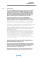
2A-6 Location X Location Y Picture Picture (optional) Audio Source Offset A A Dolby B Fax ISDN A A Dolby Fax B Key Applications Notes Post production: Soundtrack approval to picture 2 Audio Channels from X to Y, (1 Audio Channel from Y to X for code/bi-phase). Timecode Offset should be set to total path delay from Y to X to Y. This can be measured by sending timecode from Y and looping it back via X, so the offset can be read.
2A-7 Location X Location Y Picture Picture A Dolby B Fax ISDN A Dolby Fax A A Mic Applications Post production: Dubbing to picture B + Talkback Existing Audio Track Audio Mixer Mic Amp/ Audio Mixer Key Notes 2 Audio Channels from Y to X (1 used for code) 1 Audio Channel from X to Y. Audio Timecode Incoming audio at Y should be recorded on a separate medium or one that will allow offset synchronisation on relevant tracks.
2A-8 Location X Location Y Multi-track Recorder Audio Mixer Timecode Offset A Dolby B Fax A B ISDN A Dolby Fax B Multi-track Recorder Multi-track Mix A B Audio Delay Audio Mixer Mic Mic Key Applications Notes Music Recording: Mono/Stereo multi-track overdubbing 2 Audio Channels from X to Y, 2 Audio Channels from Y to X (1 used for code). Radio: Mono/two channel voice/overs Timecode Offset is only required if the session is to run in sync at both X and Y.
SECTION 3 PRE-INSTALLATION 3.1 Unpacking Before proceeding further, be sure to inspect the outer carton for shipping damage. If there has been any penetration to the carton, be sure to inspect the unit for any physical damage in those areas. Several accessories have been provided in the packet provided with this manual. Please compare them with the following list to ensure that there are no missing items: Rack screws and washers Power cord Spare fuse 1A (Part. No.
3-2 With a small flat-blade screwdriver, open the fuse compartment door in the AC power input housing (see figure below). OPEN THE DOOR FUSE ACTIVE FUSE CARRIER (LOWER) Check that the fuse in the active (lower) fuse carrier is of the correct rating. A spare fuse can be stored in the upper fuse carrier position. Snap the fuse compartment door closed. Internal Fuse The switching power supply contains a separate fuse. Most fault conditions should be protected by the main fuse.
3-3 3.4 Configuring Jumper Settings The Model DP503 includes certain user-selectable options that are configured by means of internal jumpers, as shown below. Their default settings (shipped with the unit) are shown in the figure. Any jumpers not specifically mentioned are for factory use only and should not be disturbed.
3-4 3.4.1 Clock Termination Jumper J12 [terminated] As would be appropriate for most applications, the default condition for the Send Timing inputs on the data and clock connector is terminated (by means of a 150 ohm resistor). Certain situations may require that these inputs be unterminated (e.g., multiple inputs driven from a single output). This can easily be accomplished by moving jumper J12 to the unterminated position (move jumper towards the front of unit). 3.4.
3-5 S101 Switch No. 1 2 3 4 5 6 Function Unit Address (Binary Code) Normal/Download (Baud rate set by switches 7 & 8) Baud Rate for Remote Control or Download Operation (Mode set by switch 6) 7 8 3.5.1 Up (Off) Down (On) [0] [0] [0] [0] [0] [Normal] 1 1 1 1 Download [up] [up] down down 1 Switch nos. 1-5 - Unit Address A unique address can be assigned to each DP503 in a multi-unit installation for remote control applications using the RS-232 connector J108 Rem/Download.
3-6 3.5.2 Switch no. 6 - Mode of Operation: Normal/Download The RS-232 port J108 Rem/Download can be used for 2 functions: upgrading of the audio coding algorithm software whenever upgrades are introduced, and remote control of the unit via a PC; in the latter instance upgrades can also be performed via the remote control host. Note: When invoking the download mode or using the remote control feature, , the baud rate selection switches S101-7 and S101-8 must also be set Keep switch no.
SECTION 4 INSTALLATION AND LEVEL CALIBRATION Note 4.1 For Dolby Fax connections, see Section 4.4 below for additional information. An overview of the Dolby Fax system is provided in Section 2A. Mounting The DP503 is designed for 19 inch rack mounting, but may be mounted in any plane and with any orientation. It occupies 1U (1 3/4") of space. When mounting the unit, ensure that there is air flow around it, and that it is not mounted directly above any equipment generating high amounts of heat.
4-2 AES and IEC convention calls for XLR pin 2 to be “high/hot” and pin 3 to be “low/cold.” In the interests of maintaining international standardization, we suggest that the AES and IEC recommendations be followed. In an installation where the source is unbalanced, avoid ground loops by using two conductor shielded cable exactly as for balanced circuits; in other words, ensure that the unbalancing (connecting the wire to pin 3 to ground) occurs only at the end remote from the Model DP503.
4-3 4.3.3 Terminal Adapter Control This connection is used only in a Dolby Fax installation. See Section 4.5 below. 4.3.4 Remote Control If you wish to use a PC for remote control of the DP503, connect a standard 9-pin RS-232 serial cable (not supplied) to J108 Rem/Download. Remote control operation permits access to the setting of bitstream parameters in Dolby Digital (AC-3). Refer to the manual supplied with the remote control software for instructions on its use. 4.3.
4-4 The operating level for analog signals in the Model DP503 is referenced to -18dB relative to digital full scale; in other words, the DP503 allows for 18 dB of headroom. Analog input levels in the DP503 are adjustable by means of the rear panel gain controls Gain from -18 dBu to +6 dBu, where 0 dBu is defined as 0.775 Vrms. These controls should be used in conjunction with the dual-LED calibration display Cal located adjacent to the controls (and duplicated on the front panel).
4-5 At the DP503, connect the end of the “Y” cable labeled “encoder” to J105 Encoded Data Out & Timing. At the DP524 digital audio decoder, furnished as part of the Dolby Fax system, connect the end of the “Y” cable labeled “decoder” to J103 Encoded Data In & Timing. At the ISDN unit, connect the remaining end of the “Y” cable to its mating connector at the rear of the unit, labeled HOST 1. 4.6.
4-6 console (or next piece of equipment) for the desired operating level. Refer to the manual supplied with the DP524 as necessary. Note:: The test tone level in both the DP503 encoder and DP524 decoder is referenced to -18dB relative to digital full scale. 4.6.10 ISDN Connections Attach the RJ-11 connectors for each of the ISDN lines used (1-4, typically 2) to the appropriate receptacles at the rear of the ISDN unit.
SECTION 5 OPERATION Notes: See the front and rear view figures located at the end of this section. Flow charts illustrating the user interface structure are located in Appendix C. An overview of Dolby Fax principles is described in Section 2A. An ISDN ordering guide (for North America) can be found in Appendix D. 5.1 Introduction to the User Interface The DP503 interface provides the user with all the necessary functions for controlling the unit, and, in Dolby Fax applications, the ISDN unit.
5-2 The DIRectory key is used to access the directory functions of the DP503, which enable the creation, editing, deletion, and access to entries of frequently used encoder parameters as well as, in Dolby Fax applications, frequently dialed phone numbers with their associated ISDN parameters. The SHIFT key is used to access secondary functions assigned to the other keys.
5-3 SHIFT + ENTER Insert/Contrast SHIFT + DIR ISDN Setup SHIFT + ESC Loopback During editing modes, inserts a space directly above the cursor and moves remaining text to the right. Function self-cancels after being invoked. Otherwise, invokes mode to enable adjustment of LCD screen contrast. Use Ç and È keys to adjust. Cancel by pressing ESC, Places unit into ISDN Setup mode for Dolby Fax applications. See Section 5.3.
5-4 1. Algorithm Type Data Rate Channel Mode Aux Data Rate 2. Algorithm Type Sample Rate 3. Algorithm Type Data Rate ISDN parameters (in Dolby Fax applications) The setting of a particular parameter may therefore preclude the use of certain selections in lower levels of the hierarchy; those selections are eliminated from the list of available choices when navigating the screens.
5-5 ª Use the screen above to change algorithm type, data rate, channel mode, sample rate, and auxiliary data rate (if any). Use the Å and Æ arrow keys to move back and forth among these parameters. Use the Ç and È arrow keys to bring into view the available settings for each of the parameters. Once the ENTER key or Å and Æ arrow keys are used, changes to encoder operation occur immediately. Note: There is no “undo” function.
5-6 Æ arrow key to both select the entry and move to the next parameter. Units are kbps (kilobits per second). Note: Available rates are dependent on the selected algorithm. Data rates displayed represent the total data rate. Available data rates: Display 040 048 056 064 080 5.2.
5-7 AC2 256 2C 48 12 Algorithm Type Data Rate Channel Mode Sample Rate Aux Rate Available sample rates: Label 32 44 48 5.2.5 Sample Rate (kHz) 32 44.1 48 To change Aux Rate (auxiliary data rate) AC2 256 2C 48 12 Algorithm Type Data Rate Channel Mode Sample Rate Aux Rate Use the Å and Æ arrow keys to place cursor the first character of settings in the Aux Rate column. Use the Ç and È arrow keys to scroll through available settings as shown in the table below.
5-8 5.3 ISDN Setup (for Dolby Fax applications only) Note: An overview of Dolby Fax principles is described in Section 2A. Detailed ISDN ordering information (for North America) is described in Appendix D. Important: Be sure you have installed the complete Dolby Fax system per the previous section, including connection of the ISDN lines to the ISDN unit. Otherwise, you will encounter an error message at the final stage of this procedure.
5-9 ª Use the screen above to select the switch type used by the phone company (or to select the country of use) and to conform the ISDN unit to the ISDN lines in use. Use the Å and Æ arrow keys to move back and forth among the five available parameters. Use the ENTER key to descend into subsequent menus to fully configure the multiple entries needed for each parameter. Use the Ç and È arrow keys to bring into view the available settings under sub-menus. The ESC key can be used to back up.
5-10 Note: The list of available countries continues to grow as the ISDN unit continues to gain government approvals. If your country is not listed, please contact Dolby Laboratories. 5.3.3 To configure Line 1 (L1) SW L1 L2 L3 L4 Algorithm Type Data Rate Channel Mode Sample Rate Aux Rate If you are not situated at this menu position, review the preceding sections or use the cursor keys in order to do so. With the cursor on the first character of L1, press ENTER.
5-11 Available characters: Label (space) 0 1 2 3 4 5 Label 6 7 8 9 0 # * PRI SPID1: _ Algorithm Type Data Rate Channel Mode Sample Rate Aux Rate If required by your phone company’s switch, you will be prompted to enter the SPID number associated with the primary number. Use the arrow keys as before to enter the required digits. When you have finished entering the number, press ENTER to store the number; you will then proceed to the next screen.
5-12 5.3.4 To configure Line 2 (L2), Line 3 (L3), Line 4 (L4) SW L1 L2 L3 L4 Algorithm Type Data Rate Channel Mode Sample Rate Aux Rate Phone number entry for remaining ISDN lines is identical to that of the first line. Note, however, that the designations for number and SPID will increment by successive digits to indicate the “line number.” For example, the prompt for the primary number of the second ISDN line will be designated PRI NUM2.
5-13 Note: If the ISDN unit is not powered up, if the ISDN line(s) are not connected to the ISDN unit, or if the control cable between the DP503 and ISDN unit is not connected, an error message “TA NOT READY” will be displayed. Rectify the problem and repeat the update procedure. 5.4 Using the DIRectory: Dolby Fax Applications The DP503 can store up to 48 different entries, representing either encoder parameters, complete Dolby Fax entries, or both, and can be retrieved by user-defined names.
5-14 ª Use the screen above to USE an existing directory entry; EDIT an existing directory entry; create a NEW directory entry, or DELete an existing directory entry. Use the Å and Æ arrow keys to move back and forth among the five available parameters. Use the ENTER key to descend into subsequent menus to fully configure the multiple entries needed for each parameter. Use the Ç and È arrow keys to bring into view the available settings under sub-menus. The ESC key can be used to back up.
5-15 You will then be presented with a screen that allows you to enter a name for the directory entry. NAME: _ Algorithm Type Data Rate Channel Mode Sample Rate Aux Rate Enter the name of your choice up to 13 characters in length. Use the Ç and È arrow keys to scroll through available characters as shown in the table below.
5-16 to place the cursor to the next position. When you have finished entering the number, press ENTER to store the name; you will then proceed to the next screen. Available characters: 0 1 2 3 4 5 Note: 6 7 8 9 * # SPACE Spaces can be used to make the phone number more readable. The next step allows you to edit the encoder parameters EDIT CODEC? Algorithm Type Data Rate Channel Mode Sample Rate Y N Aux Rate As usual, use the Å and Æ arrow keys and the ENTER key to make your selection.
5-17 EDIT ISDN? Algorithm Type Data Rate Channel Mode Y N Sample Rate Aux Rate As usual, use the Å and Æ arrow keys and the ENTER key to choose Y. You will then see a screen similar to the following: ÇÈ BONDING-1 64 Algorithm Type Data Rate Channel Mode Sample Rate Aux Rate Use the Ç and È arrow keys to scroll through available parameters as shown in the table below.
5-18 If you choose N, you will be presented with the following screen RE-EDIT? Algorithm Type Data Rate Channel Mode Y N Sample Rate Aux Rate If you choose Y, you will have the opportunity to check your data entry, starting at the top of the directory entry screens. If you choose N, you will exit the data entry process without saving the entry, and you will return to the first screen in the Directory mode. 5.4.2.
5-19 Continue with the remaining screens, using the arrow keys as appropriate to change only the parameters that you wish to change. 5.4.3 Using Directory Entries USE EDIT NEW DEL Algorithm Type Data Rate Channel Mode Sample Rate Aux Rate To use an existing directory entry, use the arrow and ENTER keys to select USE from the above menu. Then use the Ç and È arrow keys to scroll through your existing directory entries. Select the desired entry with the ENTER key.
5-20 5.4.4 Editing Directory Entries USE EDIT NEW DEL Algorithm Type Data Rate Channel Mode Sample Rate Aux Rate To edit an existing directory entry, use the arrow and ENTER keys to select EDIT from the above menu. Then use the Ç and È arrow keys to scroll through your existing directory entries. Select the desired entry with the ENTER key. You will then proceed to the full set of data entry screens, beginning with NAME. Use the arrow and ENTER keys as appropriate to make any desired modifications.
5-21 values displayed will depend on the previously defined state, if you or someone else have already saved a different encoder configuration. If you encounter the UPDATE TA? Y N screen, enter No by pressing the Æ arrow key so that the cursor is below the character N and then pressing ENTER. Tip: 5.5.
5-22 USE EDIT NEW DEL Algorithm Type Data Rate Channel Mode Sample Rate Aux Rate Begin by using the Å and Æ arrow keys to place the cursor on the first character of the designation NEW. Then press ENTER. You will then see the following screen: COPY ENTRY? Algorithm Type Data Rate Channel Mode Sample Rate Y N Aux Rate The purpose of the above screen is to simplify the creation of directory entries that vary only slightly from existing entries.
5-23 Available characters: A B C D E F G H I J K L M N O P Q R S T U V W X Y Z 0 1 2 3 4 5 6 7 8 9 * (begin name with asterisk) SPACE The next step allows you to edit the encoder parameters EDIT CODEC? Algorithm Type Data Rate Channel Mode Sample Rate Y N Aux Rate As usual, use the Å and Æ arrow keys and the ENTER key to make your selection. If you choose Y, you will be shown a facsimile of the default encoder screen, except that the space between parameters is in reverse video.
5-24 RE-EDIT? Algorithm Type Data Rate Channel Mode Y N Sample Rate Aux Rate If you choose Y, you will have the opportunity to check your data entry, starting at the top of the directory entry screens. If you choose N, you will exit the data entry process without saving the entry, and you will return to the first screen in the Directory mode. 5.5.2.
5-25 5.5.3 Using Directory Entries USE EDIT NEW DEL Algorithm Type Data Rate Channel Mode Sample Rate Aux Rate To use an existing directory entry, use the arrow and ENTER keys to select USE from the above menu. Then use the Ç and È arrow keys to scroll through your existing directory entries. Select the desired entry with the ENTER key. The encoder parameters associated with the selected entry will take effect immediately. 5.5.
5-26 MAIN
5-27 MAIN
MAIN
APPENDIX A INTERFACE SPECIFICATIONS AND DESCRIPTIONS A.1 DP503 Connector Pinouts A.1.1 Analog Audio Input, J101 & J102 XLR female connectors. Ch A Input, J101 Pin 1 2 3 Connection Analog signal ground Analog audio + Analog audio - Ch B Input, J102 Pin 1 2 3 A.1.2 Connection Analog signal ground Analog audio + Analog audio - AES/EBU Digital Audio Input, J103 XLR female connector. Pin 1 2 3 A.1.
A-2 A.1.4 Encoded Data Out and Timing, J105 DB-37 male connector. Pin 1 2 3 4 5 6 7 8 9 10 11 12 13 14 15 16 17 18 19 A.1.
A-3 A.1.6 TA Ctrl RS-232 Port, J107 DB-9 male connector. Pin 1 2 3 4 5 6 7 8 9 A.1.7 Connection DCD RX TX DTR Ground DSR RTS NC NC Comments direct connection to DTR asynchronous data in asynchronous data out direct connection to DCD direct connection to RTS direct connection to DSR Rem/Download RS-232 Port, J108 DB-9 female connector. Pin 1 2 3 4 5 6 7 8 9 A.1.
A-4 A.2 RS-449 Interface Description A.2.1 Functional Description The Dolby DP503 provides a standard RS-449 interface in the type DT mode (data and timing signals only, no handshakes) through a 37-pin female D-connector. RS-449 is the mechanical specification for a balanced (differential) transmission system meeting RS-422 and RS-423 electrical specifications. The Model DP503 is configured as data terminal equipment (DTE), and is typically connected to data circuit-terminating equipment (DCE).
A-5 A.2.3 Back-to-Back Testing For purposes of testing the Model DP503 and Model DP524 in a back-to-back configuration, a special cable must be constructed. Note that a DTE to DTE connection is not supported by the RS-449 specification; a standard 37-wire cable cannot be used to connect the units together. The special cable connects the TT outputs of the DP503 directly to the ST inputs of the DP503, and to the RT inputs of the DP524.
MAIN
APPENDIX B SOFTWARE DOWNLOADING PROCEDURE B.1 Introduction In the event that a software upgrade is required, the J108 Rem/Download port may be used to download the appropriate files and reprogram the Flash EEPROMs residing in the DP503. When this method of upgrade is desired, the necessary files will be supplied in IBM PC compatible format. B.2 Software Downloading Procedure 1. Connect the DP503 rear panel connector J108 Rem/Download to a standard PC serial port using a standard RS-232 cable. 2.
B-2 5. Download the required files from the PC using one of two methods: a) Use the utility SERLOAD.EXE or SERLOADN.EXE (the latter for use with Windows NT or Windows95) which are supplied with the upgrade files, by typing the command line: SERLOAD COM# BAUD FILENAME where COM# is the number of the PC serial port; BAUD is the baud rate from table above; and FILENAME is the full name of the DP503 module file to be loaded. or, b) Using any terminal emulator application, transfer the files in text mode.
B-3 the problem continues after repeating the download process, contact Dolby Laboratories. After displaying the “UPDATE COMPLETE” message for a few seconds, or in the event of an error, after displaying the error message, the DP503 will reset and enter Download mode again. If another file is to be loaded, make sure that the “READY TO LOAD…” message is displayed before sending the next file. 6. After all files have been loaded, move switch S101-6 back to its up (off) position.
MAIN
APPENDIX C DP503 USER INTERFACE STRUCTURE C.
C-2 C.
C-3 C.
C-4 C.
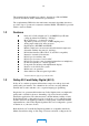
C-5 C.5 Directory Menu Operation - DEL * "CALL EDT NEW DEL" DEL Is DIR empty?` no Select Site yes "DIR EMPTY" N "DELETE N ENTRY?" Y Delete entry and reindex directory = user interface screen Other shapes = internal program functions. Within shapes, text in quotes appears on the LCD, other text idescribes functionality.
MAIN
APPENDIX D ISDN ORDERING GUIDE (NORTH AMERICA) D.1 Introduction The following ISDN ordering guide is for Dolby Fax users ordering ISDN service for the Ascend Multiband VSX ISDN terminal adapters/inverse multiplexer (hereinafter referred to as the “ISDN unit”) that is used with the Dolby Fax system, and is intended to provide answers to the basic questions that arise when ordering ISDN service.
D-2 The information the phone company needs to give you is: x The switch type that the ISDN circuits are connecting to at the CO (Central Office) x and the ISDN phone numbers for each line, and whether the B channels are 56 or 64 kbps. D.2.1 Switch Types Certain switch types (there are only two manufacturers typically encountered in North America: Northern Telecom and AT&T) require additional parameters to be defined when setting up the ISDN unit which are called SPID or Service Profile Identifier.
D-3 If your switch type is a Northern Telecom DMS-100, provide the following information to your phone company regarding the ISDN unit: Parameter Value Signaling Protocol Version Control (PVER) Functional 1 or 2 TEI Assignment Maximum Number of Keys Release Key is N or a Key Number Dynamic 3 Ringing Indicator is Y/N No EKTS is Y/N No No Notes A value of 1 is NTI custom. A value of 2 is National ISDN-1 (NI-1) and also requires a TID to be assigned as a suffix to a SPID.
D-4 B CHANNEL REQUIREMENTS x Dolby Fax locations that have and call locations with 64 kbps B channels: Two ISDN BRI Lines are required. x Dolby Fax locations that have and call locations with 56 kbps B channels: Three ISDN BRI lines are required. Also, an IXC (Inter Exchange Carrier) or long distance carrier is chosen at this point. If the phone company wires to a terminating Jack, then either RJ-11 (small) or RJ-45 (large) needs to be specified.
APPENDIX E GLOSSARY OF ISDN TERMS Basic Rate Interface (BRI) An ISDN interface that provides two 64 kbps digital B (Bearer) channels for voice or data and one 16 kbps signaling D (Delta) channel. Bonding Bandwidth ON Demand INteroperability Group, which is an industry inverse multiplexing standard for dialing, establishing, maintaining, and terminating n x 56 and n x 64 kbps calls. Channel In communications, any pathway between two devices (e.g. computers, multiplexers).
E-2 Inverse Multiplexing Inverse Multiplexing is the process of distributing a high bandwidth bitstream (like the default Dolby Fax format which operates at 256 kbps using Dolby AC-2) onto multiple ISDN BRI-channels. The default Dolby Fax format requires the ISDN unit to split up the 256 kbps bitstream into four separate calls, each at 64 kbps. Another function of inverse multiplexing is to synchronize the four calls as they travel over the ISDN network.
E-3 BONDING-1 56 This version of inverse multiplexing is identical to BONDING-1 64 but is used when connecting to either 56 kbps ISDN or Switched 56 lines. AIM DELTA 56 AIM Delta is a version of inverse multiplexing which provides compatibility between 56 kbps and 64 kbps ISDN or Switched 56 lines. In a situation where a 64 kbps site calls a 56 kbps site, 3 ISDN BRI lines are required. In the default Dolby Fax format, instead of making four calls, a Delta call places five calls for a total of 280 kbps.
E-4 Regional Bell Operating Company. There are seven RBOCs, or local phone companies, throughout the U.S. that provide local telephone service and exchange calls with the IXCs (long distance carriers). Terminal Adapter (TA) The Terminal Adapter is a device or modem which connects to the ISDN lines. The TA formats the data into the correct format and originates the dialing and signaling required by the ISDN network.