
User manual


Dolby Installation Guidelines Common Applications and Wiring
5-3
DP571
DP563
L/R
Ls/Rs
C/LFE
Main
Out
Main
Out
L/R
Ls/Rs
C/SW
1/21/2
3/43/4
5/65/6
Digital
Thru
Digital
In
7/8
Video Ref (Studio
Ref or Source VTR)
Video
Ref
Video
Ref
Thru
1/2L/R
3/4C/LFE
5/6Ls/Rs
Console
Monitor
Sends
Program
Audio
from
Console
Metadata
Out
Metadata
Input
Digital
Audio
Inputs
Console
Monitor
Returns
5.1 Program
Audio
7/8
DP570
Digital
Audio
Inputs
Digital
Emulator
Outputs
Router
Outputs
1/2
3/4
5/6
7/8
Lt/Rt
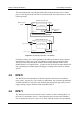
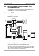
Figure 5-3 Example Equipment Setup for use with Consoles with Full Monitoring Functions
The example in Figure 5-3 shows a setup that uses separate program audio and
monitor feeds. In this example, because the DP570 digital emulator outputs are in
use, the console being used should feature the required monitoring functions. The
Lt/Rt audio is connected to the 7/8 input of the DP570. This enables metadata, which is
required for Dolby Digital broadcast of the Lt/Rt or for inclusion on a DVD, to be
associated with the Lt/Rt signal.
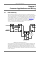
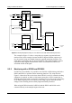
5.2.2 Monitoring with a DP569 and DP562/4
If a DP570 is not available, it is possible to use a DP562 or DP564 along with both a
DP569 and DP563 to perform similar monitoring functions. The setup shown in
Figure 5-4 shows how this can be done when a DP562 is used. No external switching
equipment is required, as either a serial remote connection, a GPI/O connection, or
the front panel can be used to control the switching. However, due to the coding delay
of the Dolby Digital process, the latency of this setup is greater than 200 ms and
changes when switching between Dolby Digital and Dolby Surround.
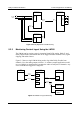
When using the DP564 instead of a DP562, both the DP563 and DP569 can be
connected directly to the multiple inputs on the unit.