DP572 Dolby E Decoder User’s Manual Issue 1 Part Number 91962
DP572 Dolby® E Decoder User’s Manual Dolby Laboratories, Inc. Corporate Headquarters Dolby Laboratories, Inc. 100 Potrero Avenue San Francisco, CA 94103-4813 USA Telephone 415-558-0200 Fax 415-863-1373 www.dolby.com European Headquarters Dolby Laboratories, Inc.
DP572 Dolby® E Decoder User’s Manual Table of Contents List of Figures................................................................................................................ v List of Tables ................................................................................................................. v Regulatory Notices ....................................................................................................... vi Fuse Information ....................................................
DP572 Dolby® E Decoder User’s Manual 4.2 4.3 Chapter 5 Hardware Description ...........................................................................5-1 5.1 5.2 Chapter 6 Firmware Update Mode.......................................................................... 4-1 Factory Reset ......................................................................................... 4-1 Front Panel............................................................................................. 5-2 5.1.1 Buttons ..
DP572 Dolby® E Decoder User’s Manual List of Figures Figure 1-1 Typical Postproduction Dolby E System......................................................1-2 Figure 1-2 Live Remote Telecast Configuration ...........................................................1-3 Figure 1-3 Network Dolby E Rebroadcast ....................................................................1-4 Figure 1-4 Local Television Transmission ....................................................................
DP571 Dolby® E Encoder User’s Manual Regulatory Notices USA This equipment has been tested and found to comply with the limits for a Class A digital device, pursuant to Part 15 of the FCC Rules. These limits are designed to provide reasonable protection against harmful interference when the equipment is operated in a commercial environment.
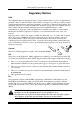
DP572 Dolby® E Decoder User’s Manual IMPORTANT SAFETY NOTICE This unit complies with the safety standard EN60065. The unit shall not be exposed to dripping or splashing and no objects filled with liquids, such as coffee cups, shall be placed on the equipment. To ensure safe operation and to guard against potential shock hazard or risk of fire, the following must be observed: o Ensure that your mains supply is in the correct range for the input power requirement of the unit.
DP572 Dolby® E Decoder User’s Manual PRODUCT END-OF-LIFE INFORMATION This product has been designed and built by Dolby Laboratories to give many years of service, and is backed by our commitment to provide high-quality support. When it eventually reaches the end of its serviceable life, it should be disposed of in accordance with local or national legislation. For current information please visit our web site: http://www.dolby.
DP571 Dolby® E Encoder User’s Manual Fuse Information WARNING: To reduce the risk of fire, replace fuses only with the same type and rating. Each unit uses a universal switching power supply that handles the full range of nominal mains voltages between 90 and 264 VAC and any frequency between 50 and 60 Hz. Check Main Fuse The main fuse rating is T 1A L (1 amp, 250 V, 20 mm, time-lag, low breaking capacity) for all operating voltages.
DP572 Dolby® E Decoder User’s Manual Internal Fuse The switching power supply contains a separate fuse. Most fault conditions should be protected by the main fuse. The internal fuse rating is F 2A L (2 amp, 250 V, 20 mm, fast-acting, low breaking capacity) for all operating voltages.
DP572 Dolby® E Decoder User’s Manual Chapter 1 Introduction Dolby® E is a professional audio data stream designed to carry up to eight channels of audio and metadata on stereo digital audio (PCM) systems, such as VTRs, servers, contribution and distribution links and within AES, SDI or HDSDI infrastructure. 1.1 Dolby E Characteristics Dolby E encoding technology: • • • • • • • • Works with existing broadcast hardware and infrastructure.
DP572 Dolby® E Decoder User’s Manual 1.3 Introduction Common Applications The DP572 is most commonly used in five applications: • • • • • 1.4 Content creation Live remote transmission Digital television network rebroadcast Local digital television transmission Play-out in satellite or cable systems Content Creation Figure 1-1 shows a typical postproduction configuration using Dolby E. A single VRef black burst signal locks all units.
DP572 Dolby® E Decoder User’s Manual 1.5 Introduction Live Remote Transmission Figure 1-2 shows a typical live remote setup. In this configuration, the multichannel output of the mixer is sent to the DP571, the DP570 and the DP563 Pro Logic II Encoder simultaneously. Metadata selections made while monitoring are sent from the DP570, to the DP571 encoder which adds this audio metadata to the 5.1 audio to make the Dolby E data stream which is then encoded into the outgoing MPEG Transport Stream.
DP572 Dolby® E Decoder User’s Manual Introduction The DP571 output then gets multiplexed with video in the MPEG transport stream and sent for distribution. 3/4 Dolby E VTR or Server 1/2 Lt/Rt Main (5.1) DP572 Lt/Rt PCM DP571 Metadata Master Control 3/4 Dolby E IRD Lt/Rt Lt/Rt Dolby E Lt/Rt MPEG Encoder PCM Metadata from DP570 Metadata Lt/Rt Main (5.1) DP572 1/2 (5.1) PCM (5.1) Lt/Rt Metadata Metadata DP570 5.1-Channel Monitor System Figure 1-3 Network Dolby E Rebroadcast 1.
DP572 Dolby® E Decoder User’s Manual Introduction Master Control Local PCM Video Control information PCM IRD DP572 DP569 Dolby Digital Dolby E MPEG Encoder Metadata Figure 1-4 Local Television Transmission 1.8 Play-out Systems In many broadcast facilities Dolby E audio is played from server or VTR through a presentation system to the transmission encoder.
Virtual Dolby Technologies Test DVD Track List iv
DP572 Dolby® E Decoder User’s Manual Chapter 2 Hardware Installation This chapter explains how to put the DP572 into service. 2.1 Unpacking and Inspection Before unpacking the unit, inspect the outer carton for shipping damage. If the carton shows damage, inspect the unit in those areas. The following accessories are provided with the unit: • • • • • • Rack screws and washers Power cord BNC 75Ω terminators, used on Digital and Video Ref inputs (Part No. 79114) Spare fuse 1 A (Part. No.
DP572 Dolby® E Decoder User’s Manual Hardware Installation type of signal present at the Main In connector and pass through baseband PCM audio when present. For more information on this capability, see Section 6.2.2. Make the following connections on the DP572: 1. Plug a stable, valid analog video reference signal into the rear of the unit. Note: If a suitable video reference signal is not present or is invalid, the DP572 will not decode a Dolby E bitstream and the PCM outputs will be muted. 2.
DP572 Dolby® E Decoder User’s Manual Chapter 3 Setup and Status Checks The DP572 has two distinct function sets, each with its own set of menus: • • Setup determines how the DP572 will be configured and how audio is decoded during the current session. Status provides constant feedback on the state of the unit and its operation. When the DP572 is powered up, the status menu appears first. Press Setup to change to the setup menu. To return to the status menu, press Shift + Setup. 3.
DP572 Dolby® E Decoder User’s Manual 3.2.1 Setup and Status Checking Main The main status screen displays the current program configuration, and the bit depth, as shown in the following example. Dolby E 5.1+2 3.2.2 20bit Decoding Frame Rate This screen displays the frame rate of the current Dolby® E stream being decoded, as shown in the following example. DE Frame Rate 29.97 fps 3.2.3 Video Ref This screen displays the video frame rate of the reference source, as shown in the following example.
DP572 Dolby® E Decoder User’s Manual 3.2.5 Setup and Status Checking PCM Input PCM Ch Dly Out No Input The PCM sample rate is displayed if present; otherwise No Input is displayed. This screen also displays the behavior of the PCM channel based on the PCM Channel Config setting. 3.2.6 Error Error Status ENTER to View When you press Enter you see two screens. First you see the number of cyclic redundancy count (CRC) and mismatch (MM) errors that have occurred since the counters were last reset.
DP572 Dolby® E Decoder User’s Manual Input Data Setup and Status Checking Dolby E Program Config 16 bit 5.1 3x2 20 bit 5.1 + 2 8x1 24 bit 5. 1+ 1 + 1 6x1 PCM 4x2 Other Output Channel Activity Main PCM In Fault Error 1 2 3 4 5 6 7 8 Remote V Ref Figure 3-1 DP572 LEDs 3.3.1 Input Data LEDs The DP572 lights the LED that corresponds to the input data bit depth. The bit depth is determined by the input Dolby E stream.
DP572 Dolby® E Decoder User’s Manual Program Config Setup and Status Checking Program and Channel Explanation One four-channel program and one two-channel program (that is, L, C, R, S, and Lt/Rt for archiving Dolby Surround soundtracks). One four-channel and two mono programs. Three stereo programs. Two stereo and two mono programs. One stereo and four mono programs. Six mono programs. One four-channel program (L, C, R, S). Two stereo programs. One stereo and two mono programs. Four mono programs. One 7.
DP572 Dolby® E Decoder User’s Manual 3.3.4 Setup and Status Checking Output Channel Activity The DP572 output channel activity LEDs display the number of channels in the currently selected program configuration, as well as their status. An LED lights up for each channel in use, and its color indicates its status. Details are listed in Table 3-3. Table 3-3 Output Channel Activity LEDs State Yellow Green Channel enabled; level <–60 dBFS. Channel enabled; level ≥–60 dBFS. Channel enabled; level ≥–0.
DP572 Dolby® E Decoder User’s Manual Chapter 4 Important Key Sequences 4.1 Warm Reset Simultaneously pressing and releasing the Shift, , and Esc keys performs a warm reset of the DP572. You can also reset the unit by unplugging it and plugging it back in. 4.2 Firmware Update Mode To put the unit into firmware update mode, follow these steps. 1. Reset the DP572. 2. During the reset, press and hold the Setup button until Ready to Load is displayed on the LCD. 4.
Virtual Dolby Technologies Test DVD Track List iv
5-1 Metadata Remote Auxiliary Status Model DP572 Dolby E Decoder 10BASE-T PCM Delay Out In 5.1 + STEREO 29.97 FPS 24BIT Main In Video Ref Shift Remote Enter Insert Esc Setup Status LTC Out Model DP572 Dolby E Decoder Dolby Laboratories Inc. San Francisco and U.K. Made in U.S.A. S/N XXXXX Dolby and the double-D symbol are trademarks of Dolby Laboratories Inc. Contrast Delete Ch 1/2 PCM 24 bit 20 bit 16 bit Input Data Ch 3/4 Digital Outputs 4x2 5.1+2 x1 5.1+2 5.
DP572 Dolby® E Decoder User’s Manual 5.1 Hardware Description Front Panel Following is a description of the front-panel components shown in Figure 5-1. 5.1.1 Buttons The primary function of each button is printed on it. Some buttons have alternate functions (printed above or below the button). To access a button’s alternate function, press the Shift button, and then press the desired button.
DP572 Dolby® E Decoder User’s Manual 5.1.3 Hardware Description Remote Connector The front panel Remote connector, used for software upgrades, is an 8-pin female mini-DIN EIA RS-232 connector. Software upgrades for the DP572 can be achieved via a remote cable connected to a standard 9-pin RS-232 PC COM port. To request an upgrade cable from Dolby Laboratories visit www.dolbysupport.com and click Got Upgrade Cable?. The pinout is shown in Table 5-2.
DP572 Dolby® E Decoder User’s Manual Hardware Description Table 5-3 DP572 Status Port Pin Functions Pin Direction 1 2 3 4 5 6 7 8 9 Output Output Output Output Output Output Input Input N/A Connection Description Dolby® E detect Reference video valid Dolby E decoding valid System operational Fault Reserved PCM channel routing PCM channel routing Ground 1—Dolby E 1—Valid 1—Valid 1—Functional 1—Functional 0—PCM or none 0—Ref video error 0—Decoding error 0—Failed 0—Hardware fault Voiceover and Swit
DP572 Dolby® E Decoder User’s Manual Hardware Description Figure 5-2 Voiceover and Switched Output Operation 5.2.2 Metadata Connector Audio metadata contained within the incoming Dolby E data stream will be sent from this connection to downstream devices, like a DP569 Dolby Digital Audio Encoder or a DP570 Multichannel Audio Tool.
DP572 Dolby® E Decoder User’s Manual Hardware Description Table 5-5 Metadata Connector Pinout 5.2.3 Pin Connection 1 Shield 2 TX A asynchronous data out – 3 RX B asynchronous data in + 4 Ground 5 NC 6 Ground 7 TX B asynchronous data out + 8 RX A asynchronous data in – 9 Shield PCM In When sending both encoded and nonencoded channel pairs to a digital recorder, the nonencoded pair must be delayed to remain synchronized with the encoded signal.
DP572 Dolby® E Decoder User’s Manual Hardware Description The DP572 supports the following frame rates: • • • • • 29.97 Hz 25 Hz 23.98 Hz 24 Hz (P or PsF) 30 Hz For the 29.97 and 25 Hz frame rates, standard black burst or color bars locked to the plant reference can be used as a video reference. All other frame rates require a Dolby DP579 Tri-Level Sync Interface to convert tri-level reference signals into Dolby Black (a signal similar to standard black burst that is compatible with the DP572).
Virtual Dolby Technologies Test DVD Track List iv
DP572 Dolby® E Decoder User’s Manual Chapter 6 Setup Menus This chapter describes the DP572 setup menus and related functions. You can find menu trees in the DP571/DP572 Dolby® E Professional Encoder/Decoder Quick Start Guide. 6.1 Operating Mode The parameters that may be set from the operating mode menu are described in the following sections. 6.1.1 Output Clock The AES outputs of the DP572 can be selectively locked to either the video reference or the main AES input.
DP572 Dolby® E Decoder User’s Manual 6.1.4 6.1.5 6.1.6 6.1.7 Hardware Description PCM Bypass • Disabled—This setting will mute the Main Outputs of the DP572 when the Main Input is PCM. This is used to mute during shuttle and jog functions from a VTR or server. • Enabled— This is the default setting; PCM audio on the Main Input will be passed to all four of the Main Outputs. Bypass Metadata • Disabled—This setting will disable the metadata output when the DP572 is in PCM Bypass.
DP572 Dolby® E Decoder User’s Manual 6.2 Hardware Description PCM Ch Config The following section describers PCM channel configuration parameters. 6.2.1 Output Routing You have five output routing choices, which are explained in Table 6-1. Table 6-1 Output Routing Options Option Delay Out Voiceover Switch Out Auto Switch Out External Ctrl Description Allows a two-channel PCM signal present at the PCM In connector to stay in sync with the decoding latency of the Dolby E audio.
DP572 Dolby® E Decoder User’s Manual 6.2.2 Hardware Description Switch Out Mode There are two user-selectable options that determine how the unit operates when Auto Switched Out mode is selected and the Main Input is invalid: 6.2.3 • No Input = Active—The audio present at the PCM input will be routed to output channels 1 and 2 while all other outputs will be muted. This is the default setting. • No Input = Mute—The unit will mute all outputs.
DP572 Dolby® E Decoder User’s Manual 6.5 • L=C R=C • L=LFE R=LFE Hardware Description System Settings Remote-control functions are not available for the DP572. Currently, this menu is used only to set parameters for firmware upgrades. 6.5.1 Unit Address The unit address may be set to a value between the default 8,280 and FFFE. 6.5.2 Unit Name Enter a unit name up to 16 characters in length. The and keys move to the previous and next letter, respectively, in the name.
Virtual Dolby Technologies Test DVD Track List iv
DP572 Dolby® E Decoder User’s Manual Appendix A Dolby Operating Specifications Description Power Input Requirements Altitude Environmental 90–264 VAC, 50–60 Hz Operating: –60 to +3000 meters (–197 to +10,000 ft) Derate max temp by 10% for every 1,000 meters Meets EIA 19” rack standard Operating, noncondensing: 0% to 98% Dimensions Humidity Nonoperating, noncondensing: 0% to 98% Operating: 0ºC to 50ºC (32ºF to 122ºF) continuous Temperature Weight Recommended Product Clearances Specification Minimum