
Inc. Home Theater System User Manual


Dolby E Multichannel Distribution System User Manual DP571 Dolby E Encoder
3-4
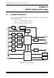
3.1.7 Main Out
The encoded Dolby E bitstream is output from the rear-panel Main Out connector as
an AES3 coaxial digital signal. Two connectors are available for transmission of
Dolby E data to multiple decoders or monitoring units.
Note: The two Main outputs are electrically separate, not passive loop-through
connections, so there is no need to terminate an unused output.
3.1.8 PCM Delay Out
Encoding delay is added to the PCM signal transmitted from the PCM Delay Out
connector. The DSP subsystem calculates the delay equivalent to the main channel latency
and applies it to the PCM Delay Out.
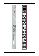
3.1.9 Status
General Purpose Input/Output (GPI/O) signals for the DP571 are available from the
Status port, a female DB-9 connector. The input and output signals are 0 – 5 V TTL.
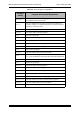
The pin configuration is defined in the table below:
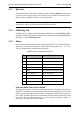
Table 3-1
DP571 Status port pin functions
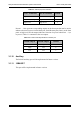
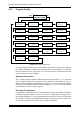
Using the Status Port to Select Presets
The two inputs on pins 7 and 8 select among the first three (of eight) presets stored in
the DP571. The inputs are normally high (internal pull-up) and trigger a preset recall by
sensing a momentary high-to-low transition. A momentary contact closure between
pins 7 and 9 (ground) or pins 8 and 9 is sufficient to activate a function but a held closure
also works. A low-to-high transition (i.e., a switch release) is ignored. Table 3-2
summarizes the operation of the two inputs.
Pin Connection Explanation
1 Preset Tally A Preset tally output
2 Reference Video Valid
1
: Valid;
0
: Ref video error
3 Dolby E Encoding Valid
1
: Valid;
0
: Encoding error
4 System Operational
1
: Functional;
0
: Failed
5Fault
1
: Functional;
0
: Hardware fault
6 Preset Tally B Preset tally output
7 Preset Ctrl A Preset control input
8 Preset Ctrl B Preset control input
9 Ground