OSLO White White •• Blanco Blanco Assembly instruction Instrucciones de instalación Local building codes vary. Please consult with your local officials for specific requirements. Las normas de construcción locales pueden variar. Póngase en contacto con los técnicos locales para conocer los requisitos locales. Review these instructions completely before beginning installation. Questions - call customer service 855-DOLLE US or 763-746-7830 - Monday - Friday 8:00-5:00 central. Metric tools required.
Part list • Parte de la lista Components & Number of Each Component Please check that all items are included before assembly 1 Componentes y Número de cada componente Verifique que todos los componentes estén incluidos antes de la entrega 2 3 ×1 K1-32030 Ø47" Ø120cm K1-32060 Ø55" Ø140cm K1-32065 Ø63" Ø160cm 12 13 14 K1-32001 ×1 K3-07013 15 ×1 K2-32018 16 1" 25mm ×1 K1-32023 17 6 5/16" 160mm 6 1/8" 155mm K1-32002 9 10 1" 25mm × 11 K1-32028 18 1 1/4" 32mm 2 3/16" 56mm ×2 × 60 × 2
9 3/8" 1000mm 30 1 9/16" 40mm ×1 K2-32520 33 34 35 ×1 K1-32080 Ø47" Ø120cm K1-32081 Ø55" Ø140cm K2-32082 Ø63" Ø160cm × 32 ×1 38 39 40 K1-32070 41 ×5 × 26 × 14 ×1 ×1 50 51 52 53 54 55 56 57 × 92 × 27 × 26 ×8 ×8 ×8 ×2 ×2 Ø6×40mm M6×6mm M6×10×20mm Ø10×70mm Ø8mm Ø8×70mm M20mm Ø20mm K1-01015 K3-10100 K3-05013 K1-32096 K3-03031 K1-32097 K3-08004 K1-32046 K3-10075 K2-32085 42 K3-90001 K3-10175 K3-03024 58 59 60 61 62 63 64 ×1 × 120 ×4 × 30 × 15 ×
Spacers for floor section Separadores de sección del piso 8 1/4" 210mm 8 7/16" 215mm 8 11/16" 220mm 15 12 3/16" 5mm ×2 ×1 13 14 4 8 7/8" 225mm 9 1/16" 230mm ×3 R1-99934-003 9 1/4" 235mm ×4 ×5 4
Spacers for treads Separadores para peldaños 8 1/4" 210mm 8 7/16" 215mm 8 11/16" 220mm 13 16 1 13 12 ×1 ×2 3/16" 5mm 8 7/8" 225mm ×3 R1-99934-004 9 1/16" 230mm ×4 9 1/4" 235mm ×5 5
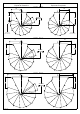
To determinate the number of spacers to use based on your staricase height: Figure on page 7: • Before installing, calculate the exact height at your stairs by measuring the distance from the upstair stairs floor to the downstairs floor vertically along the wall – see (H) • To determine the number of spacer rings required table and find staircase height (H). Example – 107 5/16” staircase height requires 3 rings on 12 treads and 1 extra ring on 5 treads.
T N 12 12 treads 12 treads 12 peldaños IMPORTANT: This is a sample diagram. To find out how many N and P rings your staircase will require — refer to the chart on page 8. N 12 N 12 IMPORTANTE: Este es un ejemplo de diagrama. Para averiguar cuántos N y P anillos su escalera requerirá - consulte la tabla de la página 8.
Number of spacer rings based on stair height inches Número de anillos separadores según la altura de la escalera pulgadas R1-99934-005 8
Number of spacer rings based on stair height metric Número de anillos separadores según la altura de la escalera unidades métricas R1-99934-005 9
Right spiral Espiral de la derecha B –+ Left spiral Espiral de la izquierda Ø47" Ø120cm A + – B 25 9/16" 650mm V A First baluster Primer balaustre First baluster Primer balaustre B Ø55" Ø140cm –+ + – A –+ Ø63" Ø160cm A V R1-99934-007 A 29 1/2" 750mm V B B 33 7/16" 850mm + – B A 10
B>0 B<0 A – + – + A distance from wall to first baluster B center of post to baluster – distance along wall V template hole to use for drilling baluster (figure 1) N treads A R1-99934-007 V V A distancia desde la pared al primer balaustre B centro del poste al balaustre distancia a lo largo de la pared V orificio de plantilla para taladrar el balaustre (figura 1) N peldaños + – 0B >> B0 A B<0 0
Assembling baluster supports to stairs Montaje de los soportes del balaustre a las escaleras 1 ½V ½V 1 We recommend the leading edge of treads be the long edge of laminated beech, rather than the end grain edge. This example shows how to place supports for a clockwise staircase.
5 2 3 13 35 3/4" 0m m 3 2 8" 5/ m m 92 13 35 3/4" 0m m 29 1/2" 750mm C= " /16 5 m 2 1 5m 7 " /16 13 mm 20 12 31 3/8" 5m m C = 25 9/16" 650mm " /16 13 mm 20 12 31 3/8" 5m m 3 Ø55" / Ø 140 cm Ø47" / Ø 120 cm 8" 5/ m 3 m 92 15 40 3/4" 0m m C = 33 7/16" 850mm 15 40 3/4" 0m m " /16 13 mm 20 Ø63" / Ø 160 cm R1-99934-015 13
Cut top landing for round opening Corte del rellano superior para abertura redonda 5R Ø47" / Ø 120 cm 11 29 4/9" 0m m 8" /1 1 1 m 3 2m 9 91 25 5/18" 0m m 8" 7/1 m 1 2 5m 7 91 25 5/18" 0m m " 7/9 m m 20 11 29 4/9" 0m m " 7/9 m m 20 Ø55" / Ø 140 cm 8" /1 1 1 m 3 2m 9 R1-99934-016 1 33 3" 0m m 1 33 3" 0m m " 7/9 m m 0 2 Ø63" / Ø 160 cm 14
6 3/16" 4mm max 1 3/16" 30mm 2 7 50 52 2 3 50 51 2 50 3 52 51 R1-99934-020 15
Assembling stair case Montaje de la escalera 8 11 4 C NOTE Installers responsibility to ensure adequate backing material is in place. Anchor sleeves (53) for concrete only. 55 54 NOTA Los instaladores deben asegurarse de garantizar el montaje de un soporte adecuado. Sólo vainas de anclaje (53) para hormigón.
13 5 14 13 2 5 18 16 1 18 13 12 4 15 16 3 9/16" 90mm Floor Suelo 4 17 6 Min.
19 18 7 20 56 57 56 7 6 57 20 6 19 18 5 R1-99934-035 5 18
20 56 57 21 22 21 Ø 3/16" [Ø 4mm] max 1 3/16" [30mm] 22 Wood | Madera: Ø 1/4" [Ø 6mm] 2 3/4" [70mm] Concrete | Hormigón: Ø 3/8" [Ø 10mm] 2 3/4" [70mm] 23 22 53 50 54 55 38 NOTE Installers responsibility to ensure adequate backing material is in place. Anchor sleeves (53) for concrete only. NOTA Los instaladores deben asegurarse de garantizar el montaje de un soporte adecuado. Sólo vainas de anclaje (53) para hormigón.
R b 20R a THIS FIGURE SHOWS TRACING OPENING EDGE If the landing is to fit into a round hole, it will have to be cut. Measure the distance from the center pole and the center point of the wall where the opstairs landing will be attached. Using a string and pencil, mark the this distance in an arch where to cut the landing. Cut using a variable saw with a fine tooth blade. Sand smooth with fine grit sand paper.
Assembling balusters to stair case Montaje de los balaustres en la escalera 24 25 CAUTION 26 PRECAUCIÓN 23 10 9 10 27 1 2 3 4 R1-99934-050 21
28 29 23 9 Wood | Madera: Ø 3/16" [Ø 4mm] 17 max 1 9/16" [40mm] Concrete | Hormigón: Ø 5/16" [Ø 8mm] max 1 9/16" [40mm] 30 8 9 50 51 17 58 NOTE Installers responsibility to ensure adequate backing material is in place. Anchor sleeves (58) for concrete only. NOTA Los instaladores deben asegurarse de garantizar el montaje de un soporte adecuado. Sólo vainas de anclaje (58) para hormigón.
31 Pull tight Aprete fuerte Slide fill fixtures (25) with set screw facing down 32 Coloque las fijaciones de los componentes (25) con el tornillo de ajuste orientado hacia abajo 25 28 7 6 28 5 25 64 3 2 1 50 2" m m 4 59 34 Start at bottom and work to top of stairs Empiece por abajo e instale de abajo hacia arriba R1-99934-060 23
Assembling railing and fill to balusters Montaje del pasamanos y componentes en los balaustres 33 - 36 33 34 26 29 i 29 Please handle very carefully – easy to scratch when mounting Por favor, manipular con mucho cuidado – puede rayarse fácilmente durante el montaje.
37 Slide fill fixtures (25) with set screw facing down.
Assembling landing balusters, railing and fill Montaje de los balaustres del rellano, pasamanos y componentes 38 39 24 35 63 23 62 11 34 28 25 59 64 34 8 52 51 R1-99934-075 26
40 26 26 42 30 60 TIP Tape cut line for smoother finish 60 CONSEJO Sujete la línea de corte para obtener un acabado más homogéneo 41 42 26 60 26 60 61 42 34 28 25 59 64 34 R1-99934-080 27
43 39 39 40 44 45 NOTE Installers responsibility to ensure adequate backing material is in place. Anchor sleeves (58) for concrete only. NOTA Los instaladores deben asegurarse de garantizar el montaje de un soporte adecuado. Sólo vainas de anclaje (58) para hormigón.