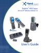
Dolphin® 9500 Series Microsoft® Windows Mobile®5.
Disclaimer Hand Held Products, Inc. (“Hand Held Products”) reserves the right to make changes in specifications and other information contained in this document without prior notice, and the reader should in all cases consult Hand Held Products to determine whether any such changes have been made. The information in this publication does not represent a commitment on the part of Hand Held Products.
Table of Contents Chapter 1 - Agency Approvals Compliance Label Locations ...............................................................................................................1-1 Laser Safety Label ........................................................................................................................1-1 Regulatory and Safety Approvals for all Dolphin 9500 Series Terminals .........................................1-2 FCC Compliance ..................................................
Drawing on the Screen ......................................................................................................................4-10 Chapter 5 - Using Dolphin Keyboards Keyboard Options................................................................................................................................5-1 Common Buttons ..........................................................................................................................5-1 Keyboard Combinations ...................
Communication Options......................................................................................................................7-1 Microsoft ActiveSync v4.1 or Higher ...........................................................................................7-1 RAS (Remote Access Services) ....................................................................................................7-1 Installing Additional Software ..........................................................................
Bluetooth LAN Access ........................................................................................................................9-8 OBEX ................................................................................................................................................9-10 Enable File Sharing .....................................................................................................................9-18 Connecting to a Bluetooth Modem........................................
HomeBase Serial Connector..............................................................................................................12-4 Charging the Main Battery ................................................................................................................12-5 To Power a Terminal and Charge its Main Battery ....................................................................12-5 Charging a Spare Battery in the Auxiliary Battery Well .....................................................
viii Dolphin® 9500 Series User’s Guide
1 Agency Approvals The Dolphin 9500 Series consists of the following terminals: Dolphin 9500 Dolphin 9550 Dolphin 9501 Dolphin 9551 For details, see Dolphin 9500 on page 3-6. For details, see Dolphin 9550 on page 3-8. For details, see Dolphin 9501 Side Panel on page 11-2. For details, see Dolphin 9551 Side Panel on page 11-4. Compliance Label Locations Dolphin terminals meet or exceed the requirements of all applicable standards organizations for safe operation.
Regulatory and Safety Approvals for all Dolphin 9500 Series Terminals Parameter Specification U.S.A. Canada European Community FCC Part 15, Class B ICES-003 EN 55022 (CISPR 22) Class B EN60950:2000 EN60825-1:1994 + A11 + A2 EN55024:1998 The CE Mark on the product indicates that the system has been tested to and conforms with the provisions noted within the 89/336/EEC Electromagnetic Compatibility Directive and the 73/23/EEC and 93/68/EEC Low Voltage Directive.
FCC Compliance Dolphin terminals meet or exceed all applicable standards and have been manufactured to the highest level of quality. Dolphin 9500 Series Batch Terminal Dolphin 9500 Series Batch terminals comply with part 15 of the FCC rules. Operation is subject to the following two conditions: (1) this device may not cause harmful interference, and (2) this device must accept any interference received, including interference that may cause undesired operation. Dolphin 9500 Series RF Terminal with 802.
RF, Regulatory, and Safety Agency Approvals for 802.11b and Bluetooth Parameter Specification RF Approvals U.S.A. Canada FCC Part 15.247 RSS 210 RF, Regulatory, and Safety Agency Approvals for GSM (MC-45 and MC-75) Parameter Specification RF Approvals U.S.A. Canada FCC Part 24 RSS 133 Dolphin 9500 Series 802.11b and/or Bluetooth R&TTE Compliance Statement Dolphin RF terminals are in conformity with all essential requirements of the R&TTE Directive (1999/5/EC).
For European Community Users Hand Held Products complies with Directive 2002/96/EC OF THE EUROPEAN PARLIAMENT AND OF THE COUNCIL of 27 January 2003 on waste electrical and electronic equipment (WEEE). Waste Electrical and Electronic Equipment Information This product has required the extraction and use of natural resources for its production. It may contain hazardous substances that could impact health and the environment, if not properly disposed.
1-6 Rev A 6/8/07 Dolphin® 9500 Series User’s Guide
2 Getting Started Congratulations on the purchase of your Dolphin mobile computer! You have made a wise choice in selecting the Dolphin, a device known worldwide for its ergonomic form factor, light-weight, rugged design and single-handed data collection capabilities. Overview Dolphin terminals are Windows Mobile-based with a unique, ergonomic shape designed for single-handed use and 64 MB RAM and 64 MB non-volatile Flash memory.
Using the Dolphin Terminal for the First Time 1. Unpack the Carton and Verify its Contents (see page 2-2) 2. Install the Main Battery Pack (see page 2-2) 3. Charge the Main and Backup Batteries (see page 2-2) 4. Initialize the Mobile Computer (see page 2-3) 5. Let Autoinstall Run (see page 2-4) 6. Set the Time and Date (see page 2-4) 7. Verify Imaging and Decoding with Demos (see page 2-4) Step 1.
Before Initial Use The terminals are shipped with both batteries discharged of all power. Charge the main battery pack for a minimum of four hours before initial use. Time to Charge Four hours for the main battery pack, eight hours for the internal backup battery the first time. Use only Dolphin 9500 Series peripherals, power cables, and power adapters. Use of peripherals, cables, or power adapters not sold/manufactured by Hand Held Products will void the warranty and may damage the terminal.
Step 6. Let Autoinstall Run For each program that loads, a status bar indicates that the program is loading. Autoinstall occurs after each hard reset. Do NOT touch the keyboard or the screen while programs are loading. All configurations of the Dolphin terminal install Demos and Power Tools. If the terminal is configured with a wireless radio, the appropriate radio drivers and utilities for each radio install. After Autoinstall is complete, the terminal performs a soft reset automatically.
Verify Decoding The Scan Demo enables you to decode a sample bar code. 1. Tap Start > Demos > Scan Demo. 2. Aim the terminal at a bar code and press the SCAN key. The scan LED lights red and an aimer beam or bracket projects out from the scanner. (The format of the aimer depends on the image engine installed in the terminal; 5000 and 5100 image engines project a green aimer beam and 5300 image engine projects an LED aiming bracket.) 3.
Resetting the Terminal There are two ways to reset the terminal: a soft and a hard reset. Soft Reset (Warm Boot) A soft reset re-boots the device without losing RAM data. You would perform a soft reset when • the terminal fails to respond. • after installing some software applications. • after making changes to certain system settings, such as network cards. 1. Press and hold the Control and the Shift keys for approximately five seconds. 2.
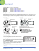
3 Hardware Overview Dolphin 9500 Series Terminals There are four terminals in the Dolphin 9500 Series: Dolphin 9500 The Dolphin 9500 terminal offers an ergonomic form factor and is the only terminal of the series that can be configured with a GSM radio. For details, see Dolphin 9500 on page 3-6. Dolphin 9550 The Dolphin 9550 terminal provides an integrated pistol grip handle for high-volume scanning applications. For details, see Dolphin 9550 on page 3-8.
Dolphin 9500 Series Peripherals Each of the following items is sold separately to enhance the capabilities of your Dolphin terminal. Dolphin HomeBase™ The Dolphin HomeBase charging and communication cradle supports both RS-232 and USB communications, which enable it to interface with the majority of PC-based enterprise systems. When a terminal is seated in the HomeBase, its main battery pack charges in less than four hours.
Dolphin 9500 Series Accessories Each of the following items is sold separately to enhance your Dolphin 9500 Series terminal’s capabilities. Note: When using accessories where the terminal is worn on the body, the terminal’s touch panel must face away from the body. Dolphin Mobile Charger The Dolphin Mobile Charger is a charging cable that connects the terminal directly to a 12 Volt DC power source, such as a cigarette lighter port inside a vehicle, eliminating the need for a cradle.
Front Panel Features This section describes features on the front panel on Dolphin 9500 Series terminals.
LEDs The two light emitting diodes (LEDs) located at the top of the LCD display flash and illuminate during resets and scanning/imaging. Both can be programmed by various software applications. Scan LED - Located in the upper right corner, this LED lights red when you press the SCAN key. Decode LED - Located in the upper left corner, this LED lights green when a scanned bar code is successfully decoded. Touch Panel Display Dolphin terminals feature a color 3.
Back Panel Features Dolphin 9500 The following graphic describes features on the back panel of the Dolphin 9500 terminal.
Image Engine Window Dolphin terminals have an optional image engine that reads and decodes linear, stacked linear (PDF417), and 2D matrix bar code symbologies. With the latest CMOS-based technology, the engine works like a digital camera and enables digital image capture, signature capture, and reading of OCR characters. Digital images taken with Dolphin terminals have a maximum image size of 640 x 480 pixels and may have up to a 256 grayscale image definition.
Dolphin 9550 This section describes the back panel of the Dolphin 9550. It contains the same features as the Dolphin 9500 described in the previous section with the additions of • • • a pistol-grip handle to hold and maneuver the terminal with greater ease, a scanner/imager trigger on the handle that activates the scan, and rubber bumpers that enable the terminal to rest safely and securely when not in use. The following is a graphic of the 9550 back panel.
Rubber Bumpers The following graphic shows the Dolphin 9550 in a nose-down position, resting on its rubber bumpers. Rubber Bumpers Stylus - inside the handle Stylus The stylus is used to operate the touch panel display. The Dolphin 9550 stores the stylus inside the pistol-grip handle.
Side Panel Features The following graphic shows the left, side panel: IrDA Port Access Door to SD Memory Audio Jack (2.5mm) IrDA Port The IrDA port communicates with IrDA-enabled devices such as PCs, printers, modems, or other Dolphin terminals. The maximum data transfer speed is 115kbps. SD Memory The access door provides user access to the industry-standard SD memory interface. You can open the access door to insert SD memory cards to expand the terminal’s memory capacity.
Bottom Panel Features Hand Strap Clip Mechanical Connector Note: Signals referenced are for a DTE device. Mechanical Connector The bottom panel features a custom, industrial-grade connector with 17 pins. When seated in a Dolphin 9500 Series peripheral, the terminal is powered, the main battery charged, and communication occurs via this connector. All Dolphin 9500 Series peripherals are designed to work exclusively with this connector.
Using the Touch Panel Hand Held Products defines proper use of the terminal touch panel as using a screen protector and proper stylus. Screen protectors maintain the ongoing integrity (i.e., prevent scratching) of the touch panel, which is why their use is recommended for applications that require a high to medium level of interface with the touch panel, such as signature capture for proof of delivery. Hand Held Products continues to advocate the use of screen protectors on all Dolphin devices.
3. Apply the touch panel protector to your device by sliding the enclosed squeegee across the surface as you peel away the backing. 4. Use the squeegee as necessary to smooth out any air pockets or bumps.
Batteries Dolphin terminals feature intelligent battery technology. There are two types of battery power: the main battery pack installed in the back panel and the backup battery located inside the terminal. They are designed to work together to prevent data loss when the terminal is in use over long periods. Both batteries must be completely charged before using a Dolphin terminal for the first time. Main Battery Pack ! Use only the Li-ion battery packs provided by Hand Held Products.
Managing Battery Power Data and files saved on Dolphin terminals may be stored in RAM memory, which does not persist through a hard reset. Therefore, to help prevent data loss, maintain a continuous power supply to the terminal. Letting the backup battery become fully discharged causes the terminal to lose all data in RAM. Therefore, you should keep a charged battery pack in the Dolphin at all times.
For more information about the RegEdit Power Tool, refer to the Dolphin Power Tools User’s Guide available for download at www.handheld.com. Checking Battery Power Tap Start > Settings > System tab > Power. The Battery tab opens displaying the charge status of both the installed Li-ion battery pack and the NiMH backup battery inside the terminal. The Power system setting contains three tabs: Battery, Wireless, and Advanced. For more information, see Power on page 6-12.
Dolphin 9500 Series Technical Specifications System Architecture Processor: Intel X-Scale PXA255 400MHz Development Environment: Dolphin SDK Add-on for Pocket PC 2003 supports Embedded Visual C++ 4.0 Dolphin .NET SDK for Pocket PC 2002 and 2003 supports Visual Studio.NET 2003 (VB.NET and C#.NET) Dolphin GSM/GPRS SDK Add-on for Pocket PC 2003 supports Embedded Visual C++ 4.0 and Visual Studio.NET 2003 Operating Platform: Microsoft Windows Mobile 5.
Dolphin 9500 Series Technical Specifications Physical Dimensions: 9500/9550 – 9.6"L x 3.45"W x 1.66"D at display (24.53 x 8.76 x 4.23 cm), 2.7"W x 1.5"D at grip (6.9 x 3.8 cm) 9501/9551 – 9.7”L x 3.45”W x 2.27”D at display (24.66 x 8.77 x 5.76 cm), 2.7"W x 1.5"D at grip (6.9 x 3.8 cm) Weight: 9500 Terminal – Batch: 19.7 oz. (558 gm), WLAN: 20.2 oz. (573 gm), WPAN: 20 oz. (567 gm), WLAN/WPAN: 20.3 oz. (576 gm) 9501 Terminal – 22.65 oz. (642 gm), all versions 9550 Terminal – Batch: 23.4 oz.
4 Using Dolphin Mobile Computers Today Screen After the Dolphin terminal initializes the first time, you see the Today screen. Tap to adjust the volume Tap to change the date and time Tap to open to change owner information Your email messages Your active tasks You can also display the Today screen anytime by tapping Start and then Today. Navigation Bar and Start Menu The Navigation bar is located at the top of the screen that displays the active program and current time.
Using the Image Engine The Dolphin terminal houses a compact image engine that instantly reads popular 1D and 2D bar codes and supports omnidirectional aiming and decoding for greater flexibility in real-world settings. The image engine can also capture digital images, such as signatures and pictures of damaged inventory.
Bar Code Symbologies Supported Symbology type Symbologies Supported 1D Symbologies Codabar Code 3 of 9 Code 11 Code 32 Pharmaceutical (PARAF) Code 93 Code 128 EAN with Add-On and EAN with Extended Coupon Code EAN-13 GS1 DataBar Interleaved 2 or 5 Matrix 2 of 5 Plessey PosiCode Straight 2 of 5 IATA Straight 2 of 5 Industrial Telepen Trioptic Code UCC/EAN-128 UPC and UPC-A 2D Symbologies Aztec Code 16K Composite Data Matrix GS1 DataBar MaxiCode OCR PDF417 QR Code Composite Codes Aztec Mesa Codablock F
Decoding The terminal supports two types of image decoding for use in various bar code reading and imaging applications: full-area imaging and Advanced Linear Decoding (ALD). Full-Area Imaging Full-area imaging provides omni-directional reading of linear and non-linear 1D and 2D bar codes, OCR, signature capture, and picture taking. When reading all bar code types using full-area imaging, a positive read can be obtained from many positions; see Dolphin 9500/9550 Scanning Position Options on page 4-5.
Dolphin 9500/9550 Scanning Position Options The aiming beams are smaller when the terminal is held closer to the code and larger when it is farther from the code. Symbologies with smaller bars or elements (mil size) should be read closer to the unit whereas symbologies with larger bars or elements (mil size) should be read farther from the unit.
Capturing Images The image-capture process is an intuitive, split-second operation for experienced users. By following the basic guidelines, new users can easily develop their own technique and, with practice, quickly learn to adapt it to different application environments. Note: The Dolphin 9501 and Dolphin 9551 do not support image capture. Image Preview When the imaging process is initiated, Dolphin touch screens display a preview of the object.
1. Tap Start > Demos > Imaging Demo > Options menu > Aimer > Enable. 2. The aiming pattern is now enabled for imaging. Note: You can also select the 2 or 5 second timeout options, which means that the aiming patter is on for 2 or 5 seconds and then shuts off automatically. Uploading Images Image files can be uploaded to a host PC via Microsoft ActiveSync and a Dolphin communication peripheral or your wireless radio connection.
File Explorer You can also use the File Explorer to find files and organize these files into folders. Tap Start > Programs > File Explorer. Tap the Up button to move up one level in the directory. You can move files in File Explorer by tapping and holding on the item you want to move, and then tapping Cut or Copy and Paste on the pop-up menu. Search The Search feature on your Dolphin terminal helps you quickly locate information. Tap Start > Programs > Search .
When you use the SIP, your terminal anticipates the word you are typing or writing and displays it above the input panel. When you tap the displayed word, it is inserted into your text at the insertion point. The more you use your Dolphin terminal, the more words it learns to anticipate. Note: To change word suggestion options, such as the number of words suggested at one time, see Input Panel Options on page 6-4. Also, a small arrow appears to the right of the button .
Drawing on the Screen Drawing on the screen is similar to writing on the screen. The difference between writing and drawing on the screen is how you select items and how they can be edited. To create a drawing, cross three ruled lines on your first stroke. A drawing box appears. Subsequent strokes in or touching the drawing box become part of the drawing. Drawings that do not cross three ruled lines will be treated as writing.
5 Using Dolphin Keyboards Keyboard Options There are three keyboards available in the Dolphin 9500 Series: 35-key numeric/alpha keyboard 43-key alpha/numeric keyboard 56-key full alpha/numeric keyboard All three keyboards • • • • • Are backlit for easy viewing in various lighting conditions. Have centrally-located keys for both right- and left-hand operation. Have keys and overlays with a silver background to enhance readability. Contain function, navigation and modifier keys.
Using the Function Keys These keys and/or functions appear on all three Dolphin 9500 Series keyboards. Name Key Function Backlight Turns the keyboard backlight on and off. Note: To see the keyboard better in low-light conditions, press the keyboard backlight button once. Backspace (BKSP) This key appears on both the 35- and 56-key keyboards. The BKSP key moves the cursor back one space each time the key is pressed. If you are typing text, it deletes the previous character each time it is pressed.
Using the Navigation Keys Located in the center of each keyboard for easy access with either hand, the navigation keys navigate the cursor through application screens. Button Function Button Function Moves the cursor up one row or line. Page up & Moves the cursor down one row or line. Page down & Moves the cursor one character to the right. Volume up & Moves the cursor one character to the left. Volume down & Note: Additional functionality varies according to the application in use.
3. Tap HKEY_LOCAL_MACHINE > HARDWARE > DEVICEMAP > KEYBD. 4. In the bottom half of the window, double-tap the StickyCtrlAlt key and change the Value Data from “0” to “1.” 5. Tap OK, then OK in the upper right corner to save the change to the registry. 6. Press the CTRL and ALT keys in combination with other keys to verify that you do not need to hold them down while you press the next key. For an example of CTRL and ALT key combinations, see General Windows Keyboard Shortcuts on page 5-13.
35-Key Numeric/Alpha Keyboard SCAN key Power key Escape key Shift key Tab key Alpha Lock key Enter key Navigation keys Alpha Lock Indicators Space key Delete key Function keys Backspace key Backlight key CTRL, Blue, Red, ALT Modifier keys Alpha Lock Key (ALPHA) The Alpha Lock key appears only on the 35-key keyboard. The Alpha Lock key enables you to toggle between the numeric and alpha modes. Numeric mode is when you type numbers with the number keys.
35-Key Blue Key Combinations Key Combination Function/Special Character Blue key + SP + Blue key + DEL - Blue key + F1 ; Blue key + F2 : Blue key + F3 / Blue key + F4 \ Blue key + BKSP START Blue key + F5 _ Blue key + F6 @ 35-Key Alpha Mode Key Combinations The 35-key keyboard defaults to numeric mode. To switch to alpha mode, press the ALPHA key once. In alpha mode, when you press a number key, you type the letter indicated by the alpha lock indicators over the key.
43-Key Alpha/Numeric Keyboard SCAN key Escape key Power key Shift key Tab key Number Lock key Enter key Navigation keys Number Lock Pad Number Lock Indicators Backlight key (use with SFT to delete) Space key (use with SFT to backspace) CTRL, Blue, Red, ALT Modifier keys Number Lock (NUM) The Number Lock key and Number Lock Pad and Indicators appear only on the 43-key keyboard. The Number Lock key enables you to toggle between the alpha and numeric modes.
43-Key Blue Key Combinations Key Combination Function/Special Character Blue key + D - Blue key + H _ Blue key + L = Blue key + P + Blue key + Q ; Blue key + R : Blue key + S * Blue key + T / Blue key + U @ Blue key + X \ Blue key + Y START 43-Key Red Key Combinations Key Combination Function/Special Character Red key + ESC Lightens Contrast* Red key + TAB Darkens Contrast* Red key + SFT Toggles on Caps Lock Red key + Q F1 Red key + R F2 Red key + S F3 Red key + T F4
43-Key Num Lock Key Combinations The 43-key keyboard defaults to alpha mode. To switch to num lock mode, press the NUM key once. In Num Lock mode, when you press a letter key, you type the number indicated by the num lock indicators over the key. Key/Key Combination Function/Special Character Press the NUM key only once to switch to num lock mode.
56-Key Full Alpha/Numeric Keyboard SCAN key Power key Escape key Backlight key Tab key Enter key Shift key Navigation keys Insert key Space key Backspace key Delete key CTRL, Blue, Red, ALT Modifier keys Note: To type a “Z” on this keyboard, press Red + Y. 56-Key Blue Key Combinations Key Combination Function/Special Character Blue key + .
56-Key Red Key Combinations Key Combination Function/Special Character Red key + ESC Lightens Contrast* Red key + TAB Darkens Contrast* Red key + SFT Toggles on Caps Lock Red key + A F1 Red key + B F2 Red key + C F3 Red key + D F4 Red key + E F5 Red key + F F6 Red key + G F7 Red key + H F8 Red key + I F9 Red key + J F10 Red key + K F11 Red key + L F12 Red key + M F13 Red key + N F14 Red key + O F15 Red key + P F16 Red key + Q F17 Red key + R F18 Red key + S F19
56-Key SFT Key Combinations Key Combination Function/Special Character SFT + 1 ! SFT + 2 @ SFT + 3 # SFT + 4 $ SFT + 5 % SFT + 6 ^ SFT + 7 & SFT + 8 * SFT + 9 ( SFT + 0 ) SFT +.
General Windows Keyboard Shortcuts Press these keys, To… CTRL + C Copy CTRL + X Cut CTRL + V Paste CTRL + Z Undo DELETE Delete CTRL + RIGHT ARROW Move the insertion point to the beginning of the next word. CTRL + LEFT ARROW Move the insertion point to the beginning of the previous word. CTRL + DOWN ARROW Move the insertion point to the beginning of the next paragraph. CTRL + UP ARROW Move the insertion point to the beginning of the previous paragraph.
5 - 14 Rev A 5/15/07 Dolphin® 9500 Series User’s Guide
6 Settings Overview Customized settings are available from the Start menu. Tap Start > Settings and settings screen opens. Settings consists of three tabs: Personal Tab System Tab Connections Tab Personal Customize buttons, set SIP options, and adjust headset settings; see Personal Tab on page 6-2. System Adjust system settings; see System Tab on page 6-8. Connections Establish network connections settings; see Connections Tab on page 6-16.
Personal Tab To access the Personal tab, tap Start > Settings. The screen opens to the Personal tab. Button Name Description See Buttons Customize keyboard buttons to perform functions. Buttons on page 6-3. Headset Adjust audio settings for headset use. Headset Control on page 6-5. Input Customize the SIP. Input Panel Options on page 6-4. Lock Password protect the terminal to limit access to your device. Menus Customize the Start and New menus.
Buttons Buttons programs keyboard buttons to launch applications or execute commands. The default button assignments that appear on the Buttons window are inactive until you enable the HotKeys Power Tool. To Enable HotKeys 1. Tap Start > Power Tools. 2. Tap the HotKeys icon once . HotKeys activates the button assignments in Buttons. 3. Verify the assignment by tapping the button on the keyboard.
Command Description Performs the same function as tapping OK on the screen. Scrolls down in the open application. Scrolls left in the open application. Scrolls right in the open application. Scrolls up in the open application. Opens the Start menu. Opens the Today screen.
Headset Control The Headset Control setting enables you to adjust audio settings while using a headset. Stereo headphone Select this option if you are using a headset for audio output only. If so, you need to use the microphone on the terminal (Microphone, page 3-7) for audio input; i.e., listen via the headset and speak into the microphone. These types of headsets usually contain two earpieces for stereo sound. Tap OK to save your selection.
Menus–Modifying the Start Menu You can add existing programs you use often, such as File Explorer, to the Start menu. You are not installing or moving the program itself, you are simply creating a shortcut to the program from the Start menu. You can modify the Start menu, • Using Menus (page 6-6), • Using File Explorer (page 6-6), or • Using ActiveSync on the Desktop (page 6-7) Using Menus 1. Tap Start > Settings > Personal tab > Menus. 2. Select the program you want to add and tap OK to save. 3.
Using ActiveSync on the Desktop You can use the Explore feature of ActiveSync on your desktop computer to navigate through the files on your Dolphin terminal. The process is essentially the same, except that you are using Windows Explorer on the PC to create and paste the shortcut. 1. Tap ActiveSync > Explore. 2. Navigate to the program. 3. Right-click on the program and select Create Shortcut. 4. Select the shortcut, right-click, and select Cut. 5. Navigate to the Start Menu folder (Windows > Start Menu).
System Tab The System tab enables you to verify and sometimes alter system parameters. To access the System tab, tap Start > Settings > System tab. Tap the appropriate icon to open that system setting. About The About system setting displays specific information about what is loaded on the terminal. It contains three tabs: Version, Device ID, and Copyrights. Version Tab Displays the information about the software, operating system, and processor of the terminal.
The Backlight Setting has two tabs: Battery and External; the options on each tab are the same. The Battery tab determines display backlight settings when the terminal is running on battery power. The External tab determines display backlight settings when the terminal is powered by an external source, such as a Hand Held Products cable. Field Description Turn off backlight Select how many minutes you want to elapse before the backlight automatically turns off.
Memory There are two kinds of memory: Main Board/IPSM 64MB RAM x 64MB non-volatile Flash Secure Digital (SD) Card Each terminal has an SD memory interface for additional application and data storage. You can order memory cards to increase memory. Each terminal contains an access door on the side panel that makes the SD memory interface user-accessible; see Access Door to SD Memory on page 3-10.
In use The MB currently being used. Free The MB that is still available for use. IPSM—Short for Internal Persistent Storage Manager, this is the 14MB of on-board Flash memory that is non-volatile. Because this memory is non-volatile, data or programs stored in IPSM are not affected when power is removed. Autoinstall programs, for example, are stored in IPSM so that they are always installed at cold-boot startup.
Power Power system settings contains three tabs: Battery, Wireless, and Advanced. Battery Tab Displays the remaining charge of both the main and backup batteries. For more information about the terminal’s batteries, see Batteries on page 3-14. Wireless Tab Determines the power settings for your wireless connection. Select Wireless signals off when you don’t want to use system power to power up the radio(s). Select Wireless signals on when you want the radio to use system power to transmit.
For On battery power, select the number of minutes of inactivity you want to pass before the terminal powers off when running on battery power. For On external power, select the number of minutes of inactivity you want to pass before the terminal powers off when running on external power. Options below the tabs Adjust backlight opens the Backlight settings so that you can make adjustments to conserve power usage; see Backlight on page 6-8.
4. Verify that the program no longer appears in the list. Screen Note: By default, dynamic screen rotation (i.e., the ability to switch between landscape and portrait orientation) is disabled on Dolphin terminals. Please consult the Dolphin SDK Add-on to find out how to enable dynamic screen rotation. There are three tabs: Alignment, Clear Type, and Text Size. Screen opens to the Alignment tab. Alignment Tab On this tab, you can re-align the screen. You first align the screen at bootup.
Text Size Tab The Text Size tab enables you to perform font scaling within certain views of the Today screen, Contacts, Calendar, Messaging, and Tasks. This means that you can increase or decrease the point size of the font on application windows. This is the default font size setting. To change the font size, move the slider toward Smallest or Largest. The Example text changes to reflect the font change. Tap OK to save the new font size setting.
Connections Tab Icon Description See 802.11b Settings Configures the 802.11b radio. This icon appears only if an 802.11b radio is installed on the terminal. Wireless LAN (WLAN) Communications with 802.11b, page 8-1 Beam Verifies and adjusts infrared settings of the IrDA port. Using Infrared, page 7-6 Connections Configures network connections; this is the Connections Manager. Connections Tab, page 6-16 IrDA Enables and disables the IrDA port so that the port can be used by the Bluetooth radio.
Server-Assigned IP Addresses Server-assigned IP addresses use Dynamic Host Configuration Protocol (DHCP). Zero-Config Wi-Fi The zero-config Wi-Fi feature of Windows Mobile is disabled on Dolphin 9500 series mobile computers. Connections Manager Microsoft’s connection manager sets up various network connections to Internet Service Providers (ISPs) via external modem. All server-assigned IP addresses use Dynamic Host Configuration Protocol (DHCP).
Proxy Server Connections If you are connected to your ISP or private network during synchronization, the terminal should download the proper proxy settings during synchronization with the PC. If these settings are not on your PC or need to be changed, ask your ISP or network administrator for the proxy sever name, server type, port, type of Socks protocol used, and your user name and password.
2. In the list, tap on an adapter to review its settings. (Server-assigned IP addresses use DHCP.) 3. If you make a change on one of these tabs, tap OK. The following message appears: 4. You must perform a soft reset to update the registry; see Soft Reset (Warm Boot) on page 2-12. During the soft reset, the new registry entries created by the changes can be read by the applications that need them. ! Do NOT perform a hard reset (see Hard Reset (Cold Boot) on page 2-12) after modifying an adapter here.
6 - 20 Rev A 5/15/07 Dolphin® 9500 Series User’s Guide
7 Communications Communication Options You can exchange information between your Dolphin terminal and other mobile devices, a desktop computer, a network, or the Internet. You have the following connection options: • Connect to your desktop computer and synchronize via Microsoft ActiveSync v4.1 or higher. • Use the infrared (IrDA) port to send and receive files between two devices.
Using ActiveSync Microsoft ActiveSync lets you synchronize information between the Dolphin terminal and the workstation. Synchronization compares the data on the desktop computer and the terminal and updates both with the most recent data so that the information on both is identical. Note: The most current version of ActiveSync can be downloaded from www.microsoft.com. Capabilities • Back up and restore your device data. • Copy (rather than synchronize) files between your device and desktop computer.
Setting up the Terminal for ActiveSync Communications 1. On the terminal, tap Start > ActiveSync > Tools > Options. OR, Start > Programs > ActiveSync > Tools > Options. ActiveSync opens displaying the PC tab. 2. Tap Menu > Connections… 3. Select Synchronize all PCs using this connection. 4. For USB communication, select ‘USB Connection from the drop-down list. For RS-232 communication, select ‘115200 from the drop-down list. 5. Tap OK.
2. Tap File > Connection Settings. 3. For USB communication, the Allow USB connection with this desktop computer box must be checked. Do NOT check Allow connections to one of the following! (USB is the default connection type.) 4. For serial (RS-232 communication), select Allow connections to one of the following: and COM1. 5. Tap OK to save settings.
The Mobile Device folder opens in Windows Explorer. The terminal is now treated as a mass storage device, and transferring files is as simple as dragging and dropping or copying and pasting as you would for moving files between folders on your hard drive. Adding Programs to the Terminal Using ActiveSync ! When selecting programs, verify that the program and version of the program are designed for Windows Mobile and your processor.
Using Infrared Dolphin terminals contain infrared or IrDA ports on the left side panel (see IrDA Port on page 3-10). Using these ports, you can send and receive data between the terminal and other devices equipped with infrared. This can include, but is not limited to, Windows Mobile information such as Contacts and Tasks, as well as software upgrades. Verify That the IrDA Port is Enabled The IrDA port must be enabled to transmit data. By default, the IrDA port is assigned to Com port 6 and is enabled.
Sending Information To send or receive, the IrDA ports of both devices - whether it’s two terminals, or a terminal and a host device - must be aligned with each other and within a close range. The maximum data-transfer speed is 115 Kbps. 1. Align the IrDA ports. 2. Open the program where you created the item you want to send and locate the item in the list. You can also beam files, but not folders, from File Explorer. 3. Tap and hold the item. A pop-up menu appears. 4. Select Beam File on the pop-up menu.
Using an ISP The communication software for creating an ISP connection is already installed on your device. Your service provider should provide the software needed to install other services, such as paging and fax services. After you are connected, you can send and receive e-mail messages by using Inbox and view web pages using Pocket Internet Explorer. For more information, see Inbox on page 11-6. You can also download software applications from the web.
Radio Options Dolphin terminals can be configured with one or a combination of 802.11b, Bluetooth, or GSM/GPRS (only available on Dolphin 9500 units) radios. For more information about 802.11b radios, see Wireless LAN (WLAN) Communications with 802.11b on page 8-1. For more information about Bluetooth radios, see Wireless PAN (WPAN) Communications with Bluetooth on page 9-1. For more information about GSM/GPRS radios, see Wireless WAN (WWAN) Communications with GSM/GPRS on page 10-1.
1. Open the Radio Manager by tapping Start > Settings > Connections tab > Radio Manager. The Radio Manager appears identifying the radios and radio combinations that can be enabled on your terminal in the Radio Modes list. (To appear on this window, a radio’s hardware module must be installed.) 2. Select the radio or radio combination and tap Apply. The Radio Manager begins enabling your radio or radio combination. 3. When enabled, the Status field reads “Success.
Com Port Assignment Table Com Port Assignment Com Port 1 Serial port. This is the 17-pin connector on the bottom panel of Dolphin terminals. Com Port 2 Bluetooth Module If there is no Bluetooth hardware installed on the terminal, this com port is unassigned. Com Port 3 Raw Infrared Com Port 4 Com Port 5 USB virtual serial port Com Port 6 IrDA, if IrDA is enabled. If IrDA is disabled, this com port becomes available. See Verify That the IrDA Port is Enabled on page 7-6. Com Ports 7-9 Unassigned.
7 - 12 Rev A 5/15/07 Dolphin® 9500 Series User’s Guide
8 Wireless LAN (WLAN) Communications with 802.11b Overview Dolphin terminals are available with an on-board 2.4 GHz 802.11b WLAN (Wireless Local Area Network) radio that uses Direct Sequence Spread Spectrum (DSSS) technology to spread the signal continuously over a wide frequency band at a data rate of up to 11 Mbps. In addition, the open software architecture makes the Dolphin terminal a complete solution for a variety of wireless mobile data collection applications.
802.11b Settings If you want to use standard WEP authentication or no authentication, you need to use 802.11b settings to configure the radio with the 802.11b Settings utility. Removing the 802.11b Wireless Security Supplement If you decide to use the 802.11b Settings utility to configure your radio, you must remove the 802.11b Wireless Security Supplement and re-boot the device. 1. Tap Start > Programs > File Explorer. 2. Drill-down to the \IPSM\Autoinstall folder. 3. Delete the .cab file named “LeWM*.
Field Description IP Address Displays the IP address of the radio. Verify configuration information with your network administrator. Renew IP Tap this button to reapply the IP address from the DHCP server when automatic DHCP is enabled. State Displays the Network Name and the MAC address of the: • AP the radio is associated with in AP mode, or • Creator of IBSS into which the radio is joined in peer-to-peer (Ad-Hoc) mode. After an SSID is chosen, this field name changes to “BSS ID.
Config Tab The Config tab provides a list of all APs and peer stations in range. Use the list to create and edit SSID profiles for APs that you want the terminal to associate with. Preferred Profiles The Preferred Profiles section displays a list of your preferred profiles, the profiles you create or add from the list of Active SSIDs below. When applied, the 802.11b radio searches for the APs in the exact order shown in the list of profiles.
Column This column displays… Channel The channel and applied WEP method, if any. =WEP Key-On =WEP Key-Off SupRate Supported data rate of the AP or the peer station. BSSID (MAC Addr) BSSID or MAC Address of the AP or the peer station. Add Tap this button to add an Active SSID to the Preferred Profiles list. Apply Tap Apply to associate your station with a selected SSID. The SSID selected can be in the Preferred Profile or Active SSIDs lists.
Status Icons Icon Description Excellent signal strength. Excellent connection. Poor signal strength. Poor connection. Radio disabled. No radio connection. (Access Point) AP Mode. Peer Station, Peer-to-Peer Mode. WEP enabled. Network needs a WEP Key to connect. WEP disabled. Network does not need a WEP Key to connect. Mismatched WEP Key configuration with your network. Online help button. To Create a New Profile In the Preferred Profiles section, tap the New button 8-6 .
Network Profile Tab Field Description Network Name &Type SSID Enter an SSID, which is the Network Name. Check with your network administrator for Network Name (SSID). TX Rate Choose the transmit rate from the drop-down list - 1MB, 2 MB, Auto 1/2 MB, 5.5 MB, 11 MB, or Fully Auto. The transmit rate is set to Fully Auto by default. Type From the drop-down list, select Peer-to-Peer=For communication between two (or more) radio stations (cards) without an AP. Access Point (AP)=Infrastructure mode.
Authentication Tab On the Authentication tab, you configure the WEP encryption key for secure wireless communication. To use WEP, the encryption key must be configured as part of the profile before connecting. For more information about configuring a profile, see To Create a New Profile on page 8-6. Field Description *Authentication Algorithm This drop-down list is active and configurable only when the WEP Key is enabled for the selected SSID profile.
Encryption Tab ! Leave the Method as Disabled. Both authentication and encryption are configured in the 802.11b Wireless Security Supplement (see page 8-12). If you must establish WEP parameters in 802.11b Settings, please remove the 802.11b Wireless Security Supplement and cold boot; see Removing the 802.11b Wireless Security Supplement on page 8-2. However, the preferred method for WEP encryption is to use the 802.11b Wireless Security Supplement.
Advanced Tab Field Description Power Save Mode This drop-down list determines the settings for Power Save Mode. • Disable=Disables the Power Save mode. • Always Enable=Enables Power Save mode. This is the default setting. • Auto Enable=Automatically enables the Power Save mode when the terminal is running on battery power and automatically disables Power Save mode when the terminal is running on external power. Slider The slider is active only if Power Save Mode is enabled.
Using the Status Icon You access the 802.11b Settings by tapping the Status icon once on the Today screen . The following menu pops up: Menu Option Description Wireless Radio On Turns on the radio. LED is on and the Link Icon displays with signal strength. Wireless Radio Off Turns off the radio. A pop-up window will ask for your confirmation. If confirmed, the LED will be off and the Status icon will change color from green to red on the top without signal strength displayed.
802.11b Wireless Security Supplement AEGIS Client® offers the most comprehensive IEEE 802.1X supplicant for securing wired and wireless networks. The Client is a standards-based implementation of IEEE 802.1X and can be configured to work with almost any network equipment–wired or wireless–that supports the 802.1X authentication standard. The Client is interoperable with 802.1X-capable wireless APs and authentication servers including Microsoft's IAS and Cisco's ACS.
Color Indicators The color of the icon indicates the status of the controlled ports. Icon Color This color icon indicates that … Green Authentication succeeded. Yellow Authentication is in process. Red Authentication failed. If there is no yellow, red or green in the icon then either the ports are not being controlled by 802.1X, or there is no authentication activity on the controlled ports. The absence of yellow, red or green may also indicate that the network access server is not an 802.
Client Menu To open the client menu, tap Client in the command bar along the bottom of the window. Menu Item Description Close Closes the Client's interface, while leaving the client running. Start/Stop Starts or stops 802.1X authentication. After you finish the initial configuration, tap the network interface and tap Start. If the port is already active, tap Stop first, then Start to force the program to read the new configuration file. Restart Same as a Stop followed by Start.
Menu Item Description Each entry is listed sequentially with a time stamp and a text message. Tap Refresh to query the log again. Tap Close to return to the main screen. Help Menu Tapping Help opens the help menu. Select Online Help to access online help. Select About to review software version information. Status Bar The status bar at the bottom of the main screen indicates the connection status between the network card and the AP.
Port Menu Options The port menu enables you to use 802.1X authentication, change the port configuration, or remove it from the port list. If there are no entries in the Port list, follow the advice in the troubleshooting section to resolve the problem. Menu Item Description Enable and Disable These commands enable or disable 802.1X authentication on the port. The port should be enabled before the protocol is started.
User Tab The User settings tab defines the protocol and the credentials used to authenticate a user. Field Description Profile Multiple user credential profiles can be created for use when the user roams from one network to another. The drop-down list contains existing authentication credential profiles. Select a profile from the list to edit it in the fields that follow. • Tapping Add permits new profiles to be added to the list. A screen appears where you can enter a name for the new profile.
Field Description Use certificate This is the certificate to be used during authentication. A certificate is required for TLS, optional for TTLS and PEAP, and unused by MD5 and LEAP. Therefore, this option becomes active only when TLS, TTLS, or PEAP is selected as the Authentication type. If Use certificate is enabled, the client certificate displayed in the field is the one that is passed to the server for verification.
System Tab The System Settings tab controls logging and the port manger timeout period. Field Description Log Level These settings control the detail of the log messages generated by the Client. Each level is cumulative. By default, all errors, warnings, and information events are logged. Each entry records a severity code (of one [debug message] to four [error] asterisks), a time stamp, and a message. • Errors - only the most severe conditions are logged. • Warnings - less severe conditions are logged.
Server Tab The Server identity tab defines the credentials the client uses to authenticate the server during TLS/TTLS/PEAP authentication message exchange. The Client uses this information to verify that the Client is communicating with a trusted server. Field Description Do not validate server certificate chain If this option is selected, the server certificate received during the TLS/TTLS/PEAP message exchange is not validated.
Wireless Networks Tab Field Description Available Networks Displays the networks the terminal recognizes as available to connect to. When the Client is first installed, there are no entries in the Available Networks list. Scan Displays a list of networks broadcasting their availability. You can also attach to networks who are not broadcasting. Move to Configured Activates after Scan has been tapped and the available networks have been retrieved.
Protocol Tab The Protocol tab configures parameters that apply to all the networks the selected port connects to. Field Description Protocol Settings These are the timer intervals and retry settings defined in the 802.1X standard. They determine how long the supplicant state machine will wait in a given state. These parameters shouldn’t be modified without an understanding of the supplicant state machine. For more information about the supplicant state machine, obtain its 802.1X protocol specification.
Configuring a Network Profile To configure a network profile, on the main screen, tap and hold on the port, tap Configure, then tap Add. The Network Profile screen opens displaying the Profile Info tab. Note: The settings on these tab windows are interrelated. This means that selecting one may disable access to others.
Profile Info Tab Field Description Network Profile Enter the name of this record. This is the name that appears in the Configured Networks list and, by default, is the same as the broadcast SSID. Note that there is nothing special about the name "default". You could configure any other record similarly and it would behave the same way. Network Name This is the SSID of the AP. If the AP broadcasts its SSID, then this value may be derived from the Available Networks list.
Field Description Key In this field, enter the WEP key. ASCII: 5 or 13 characters Hexadecimal: 10 or 26 characters. When the key entered is in the correct format, the screen changes to display the type - ASCII or Hexadecimal. Key Index/Transmit Key The Key Index drop-down list contains the available keys. You may enter up to four keys for reception; the Client will try all four to find one that works with the AP. From the drop-down list, select the key to be used for transmission as well.
Logging The event log is an ASCII text file named “LOG8021X.TXT” located in the directory defined by the WINDIR environment variable (usually the Windows directory). The information the log records is determined by the log settings on the System tab. The format of the entries is Time Stamp Message Text The Refresh button at the bottom of the screen is used to update the log file while you are reading it. If the file gets too large, old entries are automatically deleted.
3. Tap and hold on a certificate in the list. A pop-up appears asking if you want to install the certificate. 4. Tap OK. The certificate is loaded into the correct certificate store.
Advice and Workarounds Issue Possible Causes and Solutions The Client will not start on the device with an error message about missing files. Perform a soft reset. The wireless network interface (port) does not appear in the main AEGIS screen. • The license is not valid (If you have entered a time-limited license, is your clock on the device correct?). • Restart the client - on the main screen tap Client > Restart. • Perform a soft reset.
Issue Possible Causes and Solutions I cannot attach to my old network that does not support 802.1x authentication, but is using WEP encryption. • Verify that you can see your SSID in the Available Networks list on the Wireless Networks tab. Move the SSID to the top of the Configured Networks list so that it is accessed first. If the SSID is not there, you can add it manually and enter the SSID as the network name. • Select the SSID and tap Properties.
8 - 30 Rev A 5/15/07 Dolphin® 9500 Series User’s Guide
9 Wireless PAN (WPAN) Communications with Bluetooth Overview Dolphin terminals are available with a Bluetooth radio for WPAN (Wireless Personal Area Network) usage. When the Dolphin is first initialized, the *.cab file and module for Bluetooth are installed. Enabling the Bluetooth Radio Before using the radio, make sure that the Bluetooth radio is enabled. When the radio is enabled, the Bluetooth icon appears in the task tray on the Today screen.
2. Tap on the COM Ports tab. 3. As needed, view and/or enable/disable the Bluetooth COM port assignments. Tap OK. You can also disable the IrDA port to free up a port for Bluetooth devices. Tap Start > Settings > Connections tab > IrDA and select Disable IrDA Port. Note: The Bluetooth Phone port can be enabled or disabled. Object Sharing 1. Tap the Bluetooth icon that appears in the task tray on the Today screen. 2. In the pop-up menu, select Advanced Features, then My Bluetooth Device. 3.
3. Follow the Bluetooth Device Discovery Wizard to search for Bluetooth devices nearby. When prompted, select the device type you seek. 4. When the search is complete, a screen reports the discovered Bluetooth devices. Check the box next to any device you wish to save information about, (i.e., any devices you wish to connect to). Tap Next. 5. A service discovery phase begins, 5-10 seconds per chosen device. 6. In the next screen, tap Finish.
2. Tap and hold your stylus on the Bluetooth device you want to bond with. In the pop-up menu, select Bond. 3. Alternatively, after selecting a device, tap on the Bond icon. Or tap on Device, then select Bond. 4. The Bluetooth Device Bonding Wizard launches. Follow the wizard to bond with your selected device. 5. As prompted, make sure the Bluetooth device that you want to bond with is in Bondable mode.
6. If the remote device is set up to accept bonding, a Bluetooth Passkey screen appears. To continue bonding, enter the correct passkey and tap Reply. 7. When you have successfully bonded with the other device, tap Finish. View Device Properties Follow these steps to view the properties of an already discovered device. 1. If not open, launch the Bluetooth Devices folder. Tap on the Bluetooth icon on the Today screen. Select Advanced Features then Bluetooth Devices. 2. Select a device.
2. Tap on the tab for the type of device you would like to set a favorite for. If needed, use the arrow buttons to scroll and find the tab you need. Note: Tabs appears only for COM ports you have enabled. To enable a port, refer to the “Assign COM Ports” section earlier in this chapter. All tabs contain the same options for their type. 3. To select a favorite device, select Use the favorite selected above. In the drop-down list, select your device. Tap OK. 4.
Turn Radio Transmitter ON/OFF You may want to turn off the radio transmitter to save power or if you are entering an area with radio restrictions (e.g., an airplane). 1. Tap on the Bluetooth icon in the task tray on the Today screen. 2. In the pop-up menu, select Turn Transmitter OFF. 3. The Bluetooth Card radio transmitter shuts off. The Bluetooth icon and menu options turn gray. 4. To turn the radio transmitter back on, tap on the gray Bluetooth icon. In the pop-up-menu, select Turn Transmitter ON.
(c) After a successful connection is made, the status screen reports Connected. Now you are ready to synchronize files, if desired. SCENARIO #3: Your Bluetooth Devices folder contains no computers. (a) When you tap on Bluetooth ActiveSync, a Bluetooth Device Search automatically begins. Note: You can also start the device search by tapping Find in the Bluetooth Devices screen. (b) After the search is complete, select the computer you wish to ActiveSync with and tap Select.
(a) When you tap Bluetooth LAN Access, a screen appears that allows you to choose which access point to connect to in your Bluetooth Devices folder. Choose an access point from the list and tap Select. Note: If your access point is not listed, tap Find and proceed as described in Scenario #3. (b) Your device tries to connect to the selected access point. (c) If your LAN requires a passkey, a screen appears asking for the passkey. Enter the passkey, then tap OK.
(a) When you tap Bluetooth LAN Access, the device automatically begins to search for new Bluetooth devices. Note: You can also start the device search by tapping Find in the Bluetooth Devices screen. See Scenario #2. (b) After the search is complete, select the access point you wish to connect to. Tap Select. If the access point is not listed, tap Refresh to search again. (c) After you tap Select, a service discovery phase begins.
Exchange Business Cards 1. Make sure both Bluetooth devices have a business card assigned to them. If each device does not have a business card assigned to it, you cannot exchange business cards. To assign a business card to your device, do the following: • Tap on the Bluetooth icon. In the pop-up menu, tap Advanced Features > My Bluetooth Device. • Tap on the Object Sharing tab. Under My business card, tap Assign • In the next screen, select your business card and tap OK.
5. Select the Bluetooth device you wish to exchange business cards with. If the device is not listed, tap Find. 6. Your device begins exchanging business cards. After the exchange, the new business card should appear in your Contacts Send a Contact 1. Make sure the other Bluetooth device is set up to receive a contact. It must support the OBEX Object Push server profile. Refer to the documentation that came with the device for instructions.
5. Select the Bluetooth device you wish to send the contact(s) to. If the desired device is not listed, tap Find. 6. Your device processes and sends the contact(s). Send a File 1. Make sure the other Bluetooth device can receive a file; that device must support the OBEX Object Push server profile. Note: If the other device is also using the Bluetooth Connection Kit, you can set it up to receive a file by tapping the Bluetooth icon. In the pop-up menu, tap Transfer via Bluetooth > Receive Contact or File.
5. In the next screen, tap on the file you wish to send. You can use the Folder and Type drop-down menus to search for your file. Also, you can scroll horizontally to view the folder, date, size, type, and location of each file. 6. Your device sends the file. Browse Remote Device The Bluetooth File Explorer lets your device share files with another Bluetooth device. The other device must support the OBEX File Transfer server profile.
4. Select the Bluetooth device you wish to browse. If the desired device is not listed, tap Find. If the device is in the list, select it and tap Select. 5. Your device begins to establish a file sharing connection. 6. After the devices successfully connect, the Bluetooth File Explorer appears. Half of the screen shows contents of the remote device, while the other half shows contents of your device (the local device). The very bottom of the screen reports the connection status.
4. After the transfer, a copy of each selected item should appear in the other device. Create a Folder 1. Tap on the File menu. Select Remote device or Local device, wherever you want to create a folder, then tap Create remote folder or Create local folder, as applicable. 2. You can also tap and hold your stylus on an item in either the remote or local device that you wish to put in a new folder. In the pop-up menu, select Create folder. 3. In the next screen, enter a name for your new folder. Tap OK. 4.
Refresh Remote View 1. Tap on the Device menu. Select Refresh remote view. 2. Your local device begins to read the contents of the remote device. 3. After a few seconds, the contents view of the remote device is refreshed. Connect/Disconnect To connect to the remote device, do the following: 1. Make sure the remote device has file sharing enabled. 2. Start the connection process by either of two methods: • Tap Device > Connect. • Tap the Connect icon. 3.
4. If two minutes passes before you receive the item, tap Wait Again. 5. After you receive the file or contact, the “Receive Contact or File” feature is automatically disabled. Enable File Sharing 1. Tap on the Bluetooth icon. In the pop-up menu, tap Transfer via Bluetooth > Enable File Sharing. 2. The Enable File Sharing status screen appears. Your device waits two minutes for the remote device to connect. 3. After successfully connecting to the remote device, the screen reports that you are connected.
10 Wireless WAN (WWAN) Communications with GSM/GPRS The Dolphin 9500 is the only terminal in the Dolphin 9500 Series that can be configured with an integrated Siemens® GSM/GPRS quad-band radio module for WWAN communications. Overview GSM Short for Global System for Mobile communications, GSM is an open, non-proprietary wireless WAN system that is constantly evolving and growing. One of its great strengths is international roaming capability, which provides standardized dialing in more than 170 countries.
SIM Card Installation Short for Subscriber Information Module, a SIM card stores the subscriber's personal information, GSM/GPRS radio settings, security keys, contacts, etc. SIM cards are installed in compatible mobile devices, enabling you to switch devices without losing personal and setup information. SIM Card Requirements Before installing the SIM card: • The SIM card must be activated by the service provider. • The terminal must be powered down.
5. Place the SIM card door over the secured SIM card and fasten the screws. Screws SIM Card Door SIM Card SIM Card Interface 6. Install the battery pack and turn on the terminal. Audio Modes The back panel of the Dolphin 9500 contains both a speaker and a microphone that you can use to send and receive audio signals over the GSM network; see Back Panel Features on page 3-6.
Using uPhone The uPhone Application Suite contains three programs that function together to provide a complete voice, data, and text messaging solution for a mobile device fitted with a radio modem: • Dialler emulates a mobile phone and is used to make and receive telephone calls. • Call Log displays a list of the most recent calls. • SMS Manager is a text messaging program. Accessing uPhone Tap Start > Programs > uPhone. Tap one of the icons to launch the program.
Icons and Bubble Messages Icon Description Tap this icon to display: Bubble Options Good signal strength. Full signal strength. Incoming SMS message available. Tap View to display the full message in SMS Manager. This bubble appears automatically when a new SMS message is received. It contains the sender’s information and the first line of the text message. Tap Reply to switch to the SMS Manager Compose screen. The 'To:' field is autofilled with the sender’s address.
Using the Dialler The Dialler is the is the program that manages your GSM/GPRS cell phone calls. To launch the Dialler, tap Start > Programs > uPhone > Dialler. The program launches and the uPhone Dialler screen opens: Three information lines: Dialler screen Network–name of service provider. Number/Name–dialed, incoming, and outgoing calls. Status–status of the phone. Signal Strength Four bars is optimal.
• Tap the Send button . • Press the ENTER key on the keyboard. • Press the appropriate key combination on the keyboard. When the call is connected, the three information lines display the following: Network Operator Displays the name of the service provider you are using. Name/Number Displays the name and/or number you called. If the number is from your Phonebook, that entry displays. Status The status of the call. Idle - means no calls are incoming or outgoing.
Ending a Call To end or reject a call, you can: • Tap the End button . • Press the appropriate key combination on the keyboard. Call Waiting If two calls are in progress, the above options end the active call and place the other on hold. To activate the call on hold, tap Send or press ENTER or the key combination to send calls. To end the call on hold, tap End or press the key combination to end calls on the keyboard.
Button Tapping this button… End Held Drops the held call, and continues with the currently active call. Hide Closes the bubble. Touchtones To transmit touchtones for interactive voice systems while in a call, you can • Tap the 0-9, *, and # buttons on the uPhone Dialler screen. • Press 0-9 keys on the Dolphin keyboard; use the uPhone Dialler screen buttons for * and #. Dialler Menus There are three menus in the Dialler application: 1. Tools—Accesses application tools. 2.
Ringtone Configuration Different ringtones, with individual volume settings, can be set for the following: Ring Tone Sounds on an incoming call. Message Tone Sounds on an incoming SMS or Voicemail notification. Call Waiting Tone Sounds to indicate an incoming call while you are already on a voice call. You can access Ringtones two ways: 1. Tap Start > Settings > Personal tab > Ringtones icon OR 2. Open the Dialler (tap Start > Programs > uPhone > Dialler) and tap Tools > Ringtones.
Phonebook The Phonebook contains the contacts from the SIM card and Pocket Contacts. If fixed dialing is set in the SIM, then only those numbers in the fixed dialing list are shown in the Phonebook, and only these numbers can be called from the Dialler. You can access the Phonebook manually by opening the Dialler and going to Tools > Phonebook. When you tap and hold on an entry, a popup menu displays. Dial Opens the Dialler with the number entered ready for dialing.
Field Description Set maximum available Display a window for the subscriber to enter a PIN number–“PIN2”–from the subscriber. When the correct PIN is entered, the maximum available charge units for the user is set on the SIM card. USSD Short for Unstructured Supplementary Service Data, (USSD) is a technology unique to GSM that enables session-based textmessaging as opposed to SMS, which is store-and-send text-messaging.
Name The phone number or the name if the call was from or to a matching entry in the Phonebook. Time Time and date the call started. This is the local time and date. Duration Duration of the call (hours:minutes:seconds). The clock starts when the call connects, not when dialed. From the drop-down list, select the option you want to view. To see everything, select All Calls. Tools Menu Clear Deletes the entire Call Log. Exit Closes the Call Log.
uPhone Configuration uPhone Settings enable you to establish the normal operating parameters for uPhone applications. Requirements To open the uPhone configuration tools, the GSM radio must be enabled and an active SIM must be installed. The configuration tools access the network directly. If you are not connected, settings cannot be configured and you will receive an error notification when you attempt to open the configuration tools.
General Tab Field Description Phone Number This is the phone number stored on the SIM. It is displayed here for information only. Answerphone This is the number to dial to retrieve voicemail messages. To enter a new number, tap on this field and enter the digits. Call waiting Select On or Off to enable or disable call waiting functionality. Call waiting must be set to On for conference calls. PIN protection Select On or Off to enable or disable PIN protection.
The Network tab provides the ability to choose between Automatic and Manual network selection. If you choose Manual network selection, the drop-down list of available networks activates. Choose a network from this list and tap OK. A wait icon appears while the system accesses the selected network. Divert Tab The divert tab enables you to select divert options for incoming calls when you are unavailable to answer; e.g., when the phone is off, you are out of network coverage, busy, or not able to answer.
Bar Tab The Bar tab sets enables you to bar both incoming and outgoing calls. Bar outgoing calls Bar incoming calls Change barring code Select one of the following options from the drop-down list: Not barred No restrictions on outgoing calls. International calls Bar international calls. International except… Only international calls to the home country designated on the SIM card can be made. All outgoing calls Bar all outgoing calls.
Messaging Tab The Messaging tab enables you to adjust the default SMS settings. Request Delivery Reports By default, the SMS manager receives a confirmation report that each SMS message has been sent. These confirmation reports can take up valuable space and memory. Therefore, you can cancel these reports on this tab by selecting Off and tapping OK. SMS number of retries 10 - 18 This setting enables you to control the number of times the system will try to send an SMS message until the message is sent.
SMS Manager Abbreviated for Short Message Service, SMS enables the transmission of short messages (140-160 characters) to and from a cell phone. SMS messages travel over the system's control channel, which is separate from the voice channel. SMS Manager supports creation, sending, receiving, and storing of SMS text messages. Text messages sent or received can be up to 160 characters long. Opening the SMS Manager You can access the SMS Manager two ways: 1. Tap Start > Programs > uPhone > SMS Manager, OR 2.
Sent Folder The Sent folder displays sent messages. Outbox Folder The Outbox folder displays text messages waiting to be sent. Sending an SMS Message 1. In the task tray at the bottom of the screen, tap New. The new message screen opens with the cursor active in the text area. 2. Tap inside the To: field. To add the number, you can type it in or tap To: to select an entry from your Phonebook. • You must type a number that is in the appropriate international ISDN format for the country you are dialing.
Icons at the Top of the Message Screen Icon Description At the top of the window: Copy selected text. Cut selected text. Paste text. Undo the previous action. This icon appears only in a message that has been sent. Tapping this button will re-send the message. In the task tray at the bottom of the window: Send all messages in the Outbox.
GPRS Settings uPhone includes pre-configured GPRS connection profiles to connect to a GPRS network. When the GSM driver is enabled uPhone selects the appropriate pre-configured profile based on the service provider information on the installed SIM card. Before connecting to GPRS, you need to confirm and save the selected uPhone GPRS profile (or create one) in uPhone GPRS Settings, then enter the ISP information in Microsoft’s connection manager. The default profiles are for a modem connection.
5. Because GPRS is ISP technology, you need to complete the connection profile in Microsoft’s connection manager with information from your ISP. On the Connections tab, tap Connections. The connections manager opens. 6. Tap Manage existing connections. This default GPRS profile loads into the connection manager based on the service provider profile selected in uPhone’s GPRS Settings; see Step 2 above. Note: A modem connection is the default connection type.
9. Tap Next. 10. Enter the number provided by your ISP or leave the default “GPRS” if no number has been provided. If you leave “GPRS,” the GSM radio uses the APN Number entered in the uPhone profile (see Step 2 above). Tap Next. 11. Enter the User name and Password provided by your ISP. Tap Finish. Entering your user name and password here in the connection manager profile means that you don’t have to enter them every time you try to connect via GPRS. 12.
Dolphin 9501 and Dolphin 9551 Overview Dolphin 9550/9551 terminals contain the same robust features of the Dolphin 9500 Series, such as Windows Mobile 5.0 and rugged ergonomics. In addition, the Dolphin 9550/9551 terminal offer laser engine support, which enables you to scan and decode linear bar codes from greater distances. The expanded scanning and decoding capabilities combined with the terminal’s durability make Dolphin 9501/9551 terminals ideal for in-premise mobile application environments.
Front and Bottom Panel Features Dolphin 9501/9551 terminals contain the same front and bottom panel features as the other terminals in the Dolphin 9500 Series. • See Front Panel Features on page 3-4. • See Bottom Panel Features on page 3-11. Dolphin 9501 Side Panel The Dolphin 9501 contains a powerful laser engine inside a solid, flashlight form factor with a built-in finger saddle for maximum comfort.
Dolphin 9501 Hand Strap and Stylus The hand strap is attached to the finger saddle and contains two stylus loops on either side.
Dolphin 9551 Side Panel The Dolphin 9551 terminal features the same integrated pistol grip as the Dolphin 9550 for secure and versatile handling in scanintensive applications. The front end of the bottom housing accommodates the laser engine. Laser Engine The stylus is stored in the pistol-grip handle.
Radio Options Dolphin 9501/9551 terminals can be configured with one or a combination of 802.11b and Bluetooth radios. For more information about radio operations, see Using the Radio Manager on page 7-9. Keyboard Options Dolphin 9501/9551 terminals can be configured with any of the Dolphin keyboards. For more information, see Using Dolphin Keyboards on page 5-1.
11 - 6 Rev A 5/15/07 Dolphin® 9500 Series User’s Guide
Overview As the hub of your Dolphin system, the Dolphin HomeBase charging and communication cradle supports both RS-232 and USB communications, which make it able to interface with the majority of PC-based enterprise systems. When a terminal is seated in the HomeBase, its main battery pack charges in less than four hours. Power The HomeBase completes a full charge of the main battery pack in less than four hours.
Dolphin HomeBase Parts and Functions Front Panel Terminal Well Auxiliary Battery Well DOCK LED AUX Battery LED COMM LED Terminal Well Place the Dolphin terminal in this well to communicate with a host device, power the terminal, and charge its battery pack. If the host device is a desktop computer that uses ActiveSync, synchronization begins immediately. While seated in the terminal well, the main battery installed in the terminal charges.
If using the serial port This color means… Red Serial data is being sent from the Host Device to the Dolphin HomeBase. Green Serial data is being sent from the Dolphin HomeBase to the Host Device. Orange Serial data is being sent at high data rates. If using the USB port This color means… Green LED A USB Connection is established with the host computer.
Powering the HomeBase The terminal requires 9.5 Volts DC input for communications and battery charging; the Hand Held Products’ power cable contains a power adapter that converts the power source voltage accordingly. Only the power adapter cable from Hand Held Products converts the voltage appropriately. Hand Held Products recommends that you leave the Dolphin HomeBase connected to its power source at all times, so that it is always ready to use. 1.
Charging the Main Battery The Dolphin HomeBase powers the terminal and fully charges its main battery pack in less than four hours. The HomeBase contains an intelligent battery charging system that protects the battery from being damaged by overcharging. The unit senses when a battery pack is fully charged and automatically switches to a trickle charge that maintains the battery at full capacity.
Communications USB The HomeBase also supports USB communications via the USB port located on the back. The HomeBase acts as a USB device by interfacing the USB signals of the Dolphin terminal to the USB of the host workstation. Using a standard USB cable, the HomeBase’s USB interface allows the Dolphin terminal to communicate with a personal computer or to be networked through a USB hub. Dolphin terminals support USB communications out of the box.
The HomeBase can now transfer data between the terminal and the host device. If communication does not occur, check the port connections to ensure that the cradle is correctly configured. Verifying Communication You can verify that the USB driver is functioning by watching the COMM LED on the USB HomeBase. When the COMM LED illuminates solid green, the HomeBase is communicating with the host device. Verifying Data Transfer The COMM LED flashes when data is being transferred via the HomeBase.
Mounting the HomeBase Set the Dolphin HomeBase on a dry, stable surface, such as a desktop or workbench near an electrical outlet. Be sure to provide enough workspace with good lighting for the user to view and operate the Dolphin terminal while it is in the HomeBase.
Wall Mounting You can purchase a wall mount kit that contains • a mounting bracket, • three screws, and • six washer/nut sets. 1. Insert a screw into the round end of each screw slot on the bottom panel. Slide each screw towards the narrow end of the slot. Then, use a washer/nut set on each screw to secure the screw in the slot. 2. Attach the bottom panel to the mounting bracket; match the holes to the secured screws. 3.
12 - 10 Rev A 5/15/07 Dolphin® 9500 Series User’s Guide
Overview The Dolphin Mobile Base charging and communication cradle is designed specifically for in-premise and in-transit data collection applications. It features a flexible mounting bracket, a cigarette lighter adapter, and a power cable to adapt it to your environment. When a terminal is seated in the Mobile Base, its main battery pack charges in less than four hours. The serial connector supports RS-232 communication and power out to peripheral devices, such as hand held scanners.
Mobile Base Parts and Functions Front Panel The front panel of the Mobile Base has one slot. The following graphic features the Mobile Base with the Dolphin 9500 inserted into the terminal well. Terminal Well Mounting Brackets DOCK LED COMM LED Terminal Well Place the terminal in this well to communicate with a host device and charge the main battery pack. Mounting Brackets Use these to mount the Mobile Base to a fixed location.
Bottom Panel The power supply and RS-232 connectors are located on the bottom of the unit. Power Supply Connector RS-232 Communications Port Power Supply Connector Use this connector to attach a Hand Held Products power cable to the Dolphin Mobile Base. The Mobile Base can be powered by an external DC power source of between 11 VDC to 48 VDC. To run on vehicle power, you can use the 12 VDC cable or 24 VDC cable option. The appropriate cable comes with the kit you ordered.
Powering the Dolphin Terminal When seated in a Mobile Base that is connected to the appropriate power source, the Dolphin terminal receives the power to charge its main battery and run its internal circuitry. Keep the Mobile Base plugged into the power source so that the Dolphin terminal battery pack stays fully charged. For more information about powering the Mobile Base, see Powering the Dolphin Mobile Base on page 13-6.
Installing the Dolphin Mobile Base To install the Dolphin Mobile Base, you need to mount it securely to an appropriate location and supply it with power. Mounting the Mobile Base The adjustable mounting bracket holds the terminal securely in place and gives the user a variety of options for mounting the Mobile Base. When selecting a location, keep in mind that the power supply and serial connectors point straight out the bottom panel.
Spring Arm Assembly The spring arm assembly is the column that connects the latch to the back of the Mobile Base. Ball Joints There are two ball joints: one on the back of the Mobile Base and one on the mounting bracket. Both ball joints are inserted into the bracket and secured to mount the Mobile Base. Connectors The power and RS-232 connectors are located on the bottom panel. For more information, see Bottom Panel on page 13-3. Brackets Bracket The bracket contains the turnscrew and two slots.
Establishing Communication with the Mobile Base The Mobile Base RS-232 interface allows the Dolphin terminal to communicate to a personal computer, modem, or any standard RS-232 device using a standard serial cable and communications software. Requirements To use the HomeBase for communications, you need the following equipment: • • • • A Mobile Base powered by a power cable and power adapter cable from Hand Held Products The RS-232 communications cable ActiveSync v4.
RS-232 Pin Configuration Mobile Base /Host Port (DCE) IBM AT DB9 (DTE) IBM XT DB25 (DTE) Modem DB25 (DCE) Pin / Input Signal 2 / (RD) 2 3 2 3 / (TD) 3 2 3 5 / (SG) 5 7 7 4 / (DTR) 4 20 6 6 / (DSR) 6 6 20 7 / (RTS) 7 4 5 8 / (CTS) 8 5 4 Refer to this table if you want to make your own cables. To do so, you must determine if your host RS-232 device is • 9-pin or 25-pin and • configured as a DCE or DTE device.
Overview The Dolphin ChargeBase is a four-slot charging cradle that can power four Dolphin terminals, and charge their main batteries in less than four hours. Charging The Dolphin ChargeBase completes a full charge of the main battery pack in less than four hours. The ChargeBase also provides power to the intelligent battery charging system in all Dolphin terminals that senses when a full charge has been achieved and switches to a trickle charge to maintain the full charge.
Charge LEDs Each terminal well displays a Charge LED on the front that lights green to indicate charging. For details, see Charging Terminals in the ChargeBase on page 14-4. Back Panel Power Supply Connector Power Supply Connector This connector receives input from the power adapter. Plug the power connector cable from the power adapter into this connector. There is no ON/OFF switch on the back panel of the ChargeBase. The power switch is on the power adapter.
Supplying Power to the ChargeBase ! Using a non-Hand Held Products power adapter voids your warranty and could result in serious damage to the circuitry of the Dolphin ChargeBase. 1. Be sure the power switch on the power adapter is in the OFF position. 2. Plug the power cord into the power adapter. 3. Plug the power connector cable into the power connector on the back panel of the ChargeBase. 4. Plug the power cord into a standard wall outlet. 5.
Charging Terminals in the ChargeBase The Dolphin ChargeBase charges the main battery of each terminal in less than four hours. The ChargeBase uses the intelligent battery charging system incorporated into all Dolphin terminals that prevents overcharging. This means that Dolphin terminals may be stored in the ChargeBase indefinitely without damage to the terminals, battery packs, or the ChargeBase. 1. Power the ChargeBase; see Supplying Power to the ChargeBase on page 14-3. 2.
Using the DIN Rail All Dolphin charging/communication cradles have a DIN rail (7.5 X 35 mm) slot on the bottom panel to enable secure mounting. 1. Slide the DIN Rail into the DIN Rail slot on the bottom panel. 2. Turn the ChargeBase and DIN Rail right side up. 3. Secure the DIN Rail to a stable, flat horizontal surface.
Using the Wall Mount Kit Wall mount kits can be purchased separately to secure the ChargeBase to a wall or other vertical surface. For the ChargeBase, you need to purchase two kits so that you have two mounting brackets, one for each end of the ChargeBase. Each mounting bracket contains an open slot in the back to accommodate the connector cables. 1. Insert the head of each screw into the round end of each of the four screw slots on the bottom panel.
4. Using the remaining washer and nut sets, secure the mounting brackets to the bottom panel. 5. Secure the mounting brackets to an appropriate vertical surface.
14 - 8 Rev A 5/15/07 Dolphin® 9500 Series User’s Guide
QuadCharger Overview The Dolphin QuadCharger is a four-slot charging station that provides intelligent battery management for the Li-ion battery packs used in Dolphin terminals. Batteries charge in less than four hours. The fourth slot features a battery analyzer that completely resets a battery, then displays its remaining capacity. Compatibility The QuadCharger is compatible with the Li-ion batteries that power the Dolphin terminals.
Dolphin QuadCharger Parts and Functions Top Panel Status LED 1 2 3 4 SLOT 4 BATT ER CAPAC Y ITY 100% Battery Capacity LEDs 0% ANALYZ E O CHAR GE/AN Analyze Button ALYZE Charging Slots Charge/Analyze Slot Charging Slots The QuadCharger contains four charging slots. Each slot holds one Li-ion battery and charges it independently of the other slots. When a battery is placed in each slot, it immediately begins charging.
Back Panel O CHARGE/ANALYZE ALYZE 0% 0% PACITY TTERY LOT 4 1 3 2 4 Swc Power Switch Status LED Power Supply Connector Power Switch Toggle the power switch to turn the QuadCharger on and off. Power Supply Connector Use this connector to attach the power supply to the QuadCharger. The universal power supply accepts input voltages between 90-265 volts.
Inserting and Removing Battery Packs To insert a battery pack, place the end of the battery without the locking tab into the bottom of the charging pocket and snap the battery into place with a hinging motion. The Status LED for that particular slot illuminates orange when the battery has been properly inserted. To remove a battery pack, push the locking tab down and pull the battery out from the charging slot with a hinging motion.
Using the Battery Analyzer Purpose Using the Charge/Analyze slot helps you monitor the charge capacity of Li-ion batteries over time. Location The battery analyzer is located in the fourth slot - named the Charge/Analyze slot - of the ChargeBase. Only a battery placed in this slot can be run through an Analyze cycle. This slot contains Battery Capacity LEDs along the right side.
Mounting the QuadCharger The Dolphin QuadCharger should be on a dry, stable surface. To easily adapt the QuadCharger to your environment, it can be mounted on a flat, horizontal surface such as a desktop or workbench, or a flat, vertical surface such as a wall. When choosing a location, always bear in mind that • the mounting location must allow users easy access to power switch and power connector.
Wall Mounting The following graphic displays how to mount a QuadCharger to a wall: Dolphin® 9500 Series User’s Guide Rev A 5/15/07 15 - 7
Troubleshooting If you encounter problems with your Dolphin QuadCharger, refer to chart below for possible solutions. If problems persist, please contact Hand Held Products Technical Support. Problem Issue The Status LED does not come on when I insert a battery pack into the Dolphin QuadCharger Check the power connections on the Dolphin QuadCharger; make sure the POWER switch is ON and the battery pack is properly seated. The Status LED lights red during charging.
Product Service and Repair Hand Held Products provides service for all its products through service centers throughout the world. To obtain warranty or non-warranty service, return the unit to Hand Held Products (postage paid) with a copy of the dated purchase record attached. Contact the appropriate location below to obtain a Return Material Authorization number (RMA #) before returning the product. North America Telephone: Fax: E-mail: (800) 782-4263 (803) 835-8012 naservice@handheld.
Technical Assistance If you need assistance installing or troubleshooting, please call your Distributor or the nearest Hand Held Products technical support office: North America/Canada Telephone: Fax number: E-mail: (800) 782-4263 (315) 554-6705 natechsupport@handheld.com Latin America Telephone: Telephone: E-mail: (803) 835-8000 (800) 782-4263 latechsupport@handheld.com Brazil Telephone: Fax: E-mail: +55 (21) 2178-0500 +55 (21) 2178-0505 brsuporte@handheld.
Limited Warranty Hand Held Products, Inc. ("Hand Held Products") warrants its products to be free from defects in materials and workmanship and to conform to Hand Held Products’ published specifications applicable to the products purchased at the time of shipment.
16 - 4 Rev A 5/15/07 Dolphin® 9500 Series User’s Guide
Hand Held Products, Inc. 700 Visions Drive P.O.