RECORD THIS INFORMATION FOR FUTURE REFERENCE: INSTALLATION INSTRUCTIONS Model Number Serial Number Date Purchased Retailer / Qualified Installer UNIVERSAL SERIES PATIO AWNING HARDWARE STRAIGHT: 8483003.XXX, 8483004.XXX, 8484003.XXX CURVED: 838100D404, 838100D405 FRTA FABRIC ROLLER TUBE ASSEMBLY 8300, 8500, 9000 Read these instructions carefully. These instructions MUST stay with this product. REVISION D Form No. 3109969.
INTRODUCTION This awning (hereinafter referred to as “awning,” or “product”) is designed and intended for use on RVs with straight sides or curved sides, depending on model number. This awning can be installed by one person with brief help from additional personnel. Use these instructions to ensure correct installation and function of product. Keep these instructions with the awning for future reference. Dometic Corporation reserves the right to modify appearances and specifications without notice.
IMPORTANT SAFETY INSTRUCTIONS This manual has safety information and instructions to help you eliminate or reduce the risk of accidents and injuries. A. Recognize Safety Information U.S.A. This is the safety alert symbol. It is used to alert you to potential physical injury hazards. Obey all safety messages that follow this symbol to avoid possible injury or death. B.
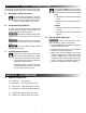
SPECIFICATIONS A. Hardware Dimensions MODEL SERIES 8483003 8483003 .401X .402X 8483004.401X 8483004.402X 8483004.
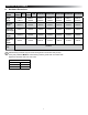
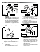
PREPARE FOR INSTALLATION A. Door Roller And Edge Guard (Optional) B. Do NOT allow cosmetic features / surfaces of product to contact floor or other hard surface. Otherwise, abrasion or other damage could occur. If potential for a squared corner entry door to contact awning fabric, a door roller kit must be installed. Rounded corner doors may NOT require a door roller kit if there is no potential for damage to awning product. 1. Install door roller. See (FIG. 1). a.
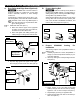
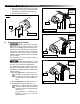
PREPARE FOR INSTALLATION FIG. 5 FIG. 7 Awning Safety Lock Roll Up RH Arm Cap 1/4”-20 Lock Nut Roll Down 1/4″-20 X 1 1/2″ Hex Head Screw Awning Safety Lock Lever Direction RH End Cap Nylon Washer Main Arm 3. Assemble main arm to torsion rod of FRTA, with nail (in end cap) opposite main arm. 4. Place 1/4″-20 X 1 1/2″ hex head screw (with washer) through main arm, cap, and torsion rod, securing with 1/4″-20 lock nut. Tighten to 7.34 9.03 N·m torque. See (FIG. 7). 5.
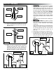
PREPARE FOR INSTALLATION a. With both hardware arms secured to FRTA and front of arms down, rotate left arm clockwise slightly to release pressure from nail. b. Remove nail and lower arm. FIG. 10 Top Mounting Bracket FIG. 9 FRTA Nail Awning Rail Mounting Over Rail LH End Cap E. FIG. 11 Top Mounting Bracket Determine Awning Location 1. IMPACT OR CRUSH HAZARD.
PREPARE FOR INSTALLATION FIG. 13 FIG. 14 Top Mounting Bracket Top Bracket Spacer Awning Rail With Drip Channel Arm Assemblies 2. Make sure arm assemblies do not restrict use of doors, windows, etc. See (FIG. 14). INSTALL AWNING A. Insert Awning Fabric Into Awning Rail 3. While one person guides awning fabric into awning rail, carefully move (carry) awning assembly to predetermined location. See (FIG. 15). To determine correct awning location, see subsection, "E.
INSTALL AWNING 4. FIRE OR ELECTRICAL SHOCK HAZARD. Make sure there are no obstacles (wires, pipes, etc.) inside RV’s roof and / or walls. Shut OFF gas supply, disconnect 220-240 Vac power from RV, and disconnect positive (+) 12 Vdc terminal from supply battery BEFORE drilling or cutting into RV. Failure to obey these warnings could result in death or serious injury. Drill 4.76mm diameter holes through marked mounting hole locations and into solid structure of RV. Drill 5.
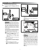
INSTALL AWNING C. Install Bottom Mounting Brackets FIG. 21 1. Latch bottom mounting bracket onto patio foot (located on bottom of adjustable arm). See (FIG. 20). Bottom Spacer Main Arm FIG. 20 Adjustable Arm RV Molding Adjustable Arm Bottom Mounting Bracket Patio Foot 4. Square arm assembly to RV and FRTA. See (FIG. 22). Measuring from a door or window frame is acceptable. Bottom Mounting Bracket 2. Make sure top casting is still resting on top mounting bracket’s top pivot. See (FIG. 19).
INSTALL AWNING E. 7. ALWAYS use sealant on (clean) parts and surfaces where fasteners enter RV’s roof and / or walls. Otherwise, water leakage could occur. Apply sealant to #14-10 X 1 3/4” hex head screw threads. Then place and tighten screws through bottom mounting bracket and into solid structure of RV. 8. Repeat steps (1) through (7) for opposite side. D. Release Tension 8500/9000 Awning Preset 1. IMPACT OR PINCH HAZARD.
INSTALL AWNING Removing nails will release the factory preset tension. To facilitate removal, you may need to twist the fabric roller tube (as if unrolling awning) by pulling the bottom of tube toward you while pulling on nail. a. Hold strap securely. b. Rotate awning safety lock to roll up position, allowing awning to roll up against RV surface. FIG. 25 a. If there is misalignment, make adjustments accordingly. b. Cycle awning again to check alignment. 3.