
Installation Guide


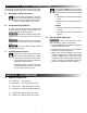


10
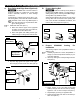
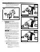
FIG. 21
Bottom Mounting Bracket
Bottom Spacer
RV Molding
Adjustable
Arm
Main Arm
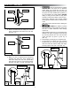
4. Square arm assembly to RV and FRTA. See
(FIG. 22).
Measuring from a door or window frame is
acceptable.
FIG. 22
Floor Line
Square
To RV
And
FRTA
FRTA
Arm Assembly
5. While holding bottom mounting bracket against
RV wall, mark hole locations. See (FIG. 20) &
(FIG. 22).
6. FIRE OR ELECTRICAL SHOCK
HAZARD. Make sure there are no obstacles
(wires, pipes, etc.) inside RV’s roof and / or
walls. Shut OFF gas supply, disconnect 220-240
Vac power from RV, and disconnect positive (+)
12 Vdc terminal from supply battery BEFORE
drilling or cutting into RV. Failure to obey these
warnings could result in death or serious injury.
Drill 4.76mm diameter holes through marked
mounting hole locations and into solid structure
of RV.
Drill 5.56mm diameter holes if drilling into
steel.
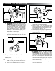
INSTALL AWNING
C. Install Bottom Mounting Brackets
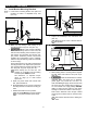
1. Latch bottom mounting bracket onto patio foot
(located on bottom of adjustable arm). See
(FIG. 20).
FIG. 20
Bottom Mounting
Bracket
Adjustable
Arm
Patio Foot
2. Make sure top casting is still resting on top
mounting bracket’s top pivot. See (FIG. 19).
3. IMPACT OR CRUSH HAZARD.
Make sure mounting surface on RV is at, has
solid structural backing where fasteners pene-
trate surface, and will safely and securely sup-
port product. Otherwise, product may become
unstable and could [detach / bend / collapse].
Failure to obey this warning could result in death
or serious injury.
Find a solid structure in RV wall to install bottom
mounting bracket. Then adjust arm to place bot-
tom mounting bracket in desired mounting posi-
tion. See (FIG. 16), (FIG. 20), & (FIG. 21).
Mount directly into RV oor line, over
molding, etc. If installing over RV molding,
a bottom spacer MUST be used.
See subsection, "A. Optional Compo-
nents" on page (3) to order bottom
spacer kits.
a. While one person holds and controls main
arm, pull lift handle out.
b. Slide adjustable arm up or down until bottom
mounting bracket is in desired mounting po-
sition
c. Release lift handle to lock in position.
Lift handle MUST be locked in position
to complete installation (later steps).