
Installation Guide


6
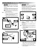
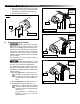
FIG. 7
RH Arm Cap
Main
Arm
1/4″-20 X 1 1/2″
Hex Head Screw
Nylon Washer
1/4”-20
Lock Nut
3. Assemble main arm to torsion rod of FRTA, with
nail (in end cap) opposite main arm.
4. Place 1/4″-20 X 1 1/2″ hex head screw (with
washer) through main arm, cap, and torsion rod,
securing with 1/4″-20 lock nut. Tighten to 7.34 -
9.03 N·m torque. See (FIG. 7).
5. Repeat steps (2) through (4) for opposite side.
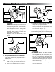
6. Be sure awning safety lock is in roll down posi-
tion. See (FIG. 8).
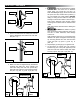
FIG. 8
Awning
Safety Lock
Awning Safety
Lock Direction
Roll Down
Roll Up
RH End Cap
7. IMPACT OR PINCH HAZARD.
Do NOT remove nail from torsion rod (at end
cap) until BOTH arm caps are secured to cor-
responding main arms, and awning safety lock
lever is in roll down position. Otherwise, rapid
casting spin off will occur. Spring tension will at-
tempt to close the awning quickly and unexpect-
edly. Failure to obey this warning could result in
death or serious injury.
Remove nail from left end of torsion rod (LH end
cap) only. See (FIG. 9).
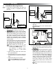
FIG. 5
Roll Down
Roll Up
Awning Safety
Lock Lever
Direction
Awning
Safety Lock
RH End Cap
6. IMPACT OR PINCH HAZARD.
Do NOT remove cotter pin from torsion rod (at
end cap) until BOTH top castings are secured
to corresponding main arms, and awning safety
lock lever is in roll down position. Otherwise,
rapid casting spin off will occur. Spring tension
will attempt to close the awning quickly and un-
expectedly. Failure to obey this warning could
result in death or serious injury.
Straighten, remove, and discard cotter pin from
left end of torsion rod (LH end cap) only. See
(FIG. 6).
FIG. 6
LH End CapCotter Pin
D. Prepare 8300 Awning For Installation
The awning requires minor preparation before in-
stalling on RV.
1. Carefully lay FRTA on a clean, well padded “V”
trough (or other well protected surface) to pre-
vent fabric damage.
2. Insert arm cap into RH main arm. See (FIG. 7).
PREPARE FOR INSTALLATION