Installation Instructions Absorption Refrigerator for Recreation Vehicles RMD 8501 RMD 8551 RMD 8505 RMD 8555 T.B.
Dometic GmbH In der Steinwiese 16 D-57074 Siegen www.dometic.
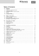
Table of Contents 1.0 General . . . . . . . . . . . . . . . . . . . . . . . . . . . . . . . . . . . . . . . . . . . . . . 4 1.1 1.2 1.3 1.4 1.5 1.6 1.7 Introduction . . . . . . . . . . . . . . . . . . . . . . . . . . . . . . . . . . . . . . . . . . . . . . . . . . . . . . . . . . . . . . . . Guide to these operating instructions . . . . . . . . . . . . . . . . . . . . . . . . . . . . . . . . . . . . . . . . . . . . Copyright protection . . . . . . . . . . . . . . . . . . . . . . . . . . . . . . . . . .
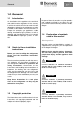
General 1.0 General 1.1 Introduction No part of these instructions may be reproduced, copied or utilised in any other way without written authorisation by Dometic GmbH, Siegen. On installation of the appliance, the technical and administrative regulations of the country in which the vehicle will first be used must be adhered to. Otherwise the refrigerator must be installed as described in these instructions.
General CAUTION! 1.6 All information and guidance in these operating instructions were prepared after taking into consideration the applicable standards and regulations as well as the current state of the art. Dometic reserves the right to make changes at any time which are deemed to be in the interest of improving the product and safety.
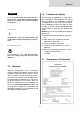
Safety instructions 2.0 Safety instructions 2.1 Application according to regulations DANGER! Never use an unshielded flame to check gas bearing parts and pipes for leakage! This refrigerator is designed for installation in recreation vehicles such as caravans or motorhomes. The appliance has been typeapproval tested for this application in accordance with the EC Gas Directive. There is a danger of fire or explosion.. The refrigerator is to be used solely for storing foodstuffs.
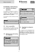
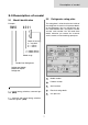
Description of model 3.0 Description of model 3.1 3.2 Model identification Example : RM D Refrigerator rating plate The rating plate is to be found on the inside of the refrigerator. It contains all important details of the refrigerator. You can read off from this the model identification, the product number and the serial number. You will need these details whenever you contact the customer service centre or when ordering spare parts.
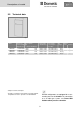
Description of model 3.3 Technical data Fig. 2 Model RMD 8501 RMD 8505 RMD 8551 RMD 8555 Dimensions Gross capacity H x W x D (mm) with Depth incl. door freezer compartment Rating details mains/battery Consumption * electricity/gas over 24hrs Net weight Ignition Piezo Automat 1245x525x567 160 lit. 160 lit. 30 lit. 190 W / 170 W ca.3,2 KWh / 380 g 40 kg • 30 lit. 190 W / 170 W ca.3,2 KWh / 380 g 40 kg • 1245x525x622 190 lit. 35 lit. 190 W / 170 W ca.
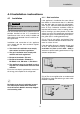
Installation 4.0 Installation instructions 4.1 4.1.1 Side installation Installation If the appliance is installed on the same side of the vehicle as the entrance door, it is desirable that the door does not cover the refrigerator's vents. (Fig. 5, Clearance door/ventilation grille at least 25 mm). Otherwise ventilation could be impaired which causes a loss in cooling perfor− mance. Awnings are often placed at the door side of a caravan.
Installation 4.1.2 Rear installation CAUTION! Rear installation often causes an unfavourable installation arrangement, as ideal ventilation cannot always be assured (e.g. the lower ventilation grille is covered by the bumper or the rear lights of the vehicle!). The maximum cooling performance of the aggregate is actually not available.
Installation Dometic recommend mounting a strip with a heat deflector plate into the installation recess above the appliance (Fig. 8). This allows the ascending hot air to escape directly outside. This deflection plate must also be provided with a lipped seal. That ensures that the refrigerator can easily be removed for maintenance or repair. Deviations require the consent of the manufacturer! 4.
Installation 4.2.1 Installation of roof exhaust R500 and lower ventilation grille LS300. 4.2.2 Installation of lower and upper ventilation grilles LS300. R500 Minimum height of ventilation Minimum height of ventilation R500 H ventilation aperture d = 20 - 40 mm ventilation aperture d = 20 - 40 mm Fig. 11 ☺☺☺ 1250 ☺☺ 1400 3. Upper vent grille LS300 lower vent grille L205 Fig. 12 The ventilation grilles must have an open cross-section of at least 400 cm².
Installation 4.3 Installing the ventilation system 4.3.1 Installing LS300 To install the ventilation grilles, cut two rectangles width b = b490mm, height a 249mm, in the outer wall of the vehicle (for position of the cuts, see Fig. 11,12).). 1 Cut two rectangles in the outer wall of the vehicle. Correct mounting of the lower ventilation grille facilitates access to the connections and functional parts during maintenance. 4.3.
Installation 4.3.3 Installing L205 (without mosquito net) 4.3 To install the ventilation grille, cut a rectangle width 451 mm x height 156 mm, in the outer wall of the vehicle (for position of the cuts, see Fig. 11,12). 1 Seal the mounting frame making it waterproof (does not apply for mounting frames with integral seal). Exhaust duct system The exhaust gas duct system must be made in such a manner as to achieve a complete extraction of combustion products to the outside of living space.
Installation 4.5 4.6 Installation recess The refrigerator must be installed draught-proof in a recess (also refer to Section "4.1.3"). The measurements of the recess are stated in the table below. Push the appliance far enough into the recess until the front edge of the refrigerator casing is aligned with the front of the recess. Allow a gap of 15-20 mm between the back wall of the recess and the refrigeration unit.
Installation 4.7 CAUTION! Insert the decor panel Decor panel with frame Remove the lateral ledge (1) 1 from the door (ledge is attached, not screwed). Shift decor panel (2) 2 away from the door and insert the new decor panel. Re−attach ledge (1) 1 . Fig. 32 Fig. 31 wrong 2 right 1 Frameless decor panel 1 2 Fig. 29 Fig. 33 4 2 3 1 2 Decor panel dimensions : 1 Upper door Height Width Thickness 300 +/- 1 mm 507,5 +/- 1 mm max. 1.7 mm Lower door Fig.
Installation 4.8 Gas installation be issued. WARNING! The refrigerator must be equipped with a shut−off valve allowing to cut the supply line. Such a shut−off device must be rea− dily accessible to the user. The gas connection shall be carried out by qualified personnel* only. * Qualified personnel are accredited experts who are able, by virtue of their training and knowledge, to vouch for the correct implementation of the leakage test. Observe the regulations stated in section 4.1.
Installation 4.9 Electrical installation 4.9.2 Battery connection The machine's 12V connection cable is connected (observing correct polarity) to a terminal strip. The wiring for the heating element (refer to A, B wiring diagram connections; connection cable white/red) must be direct and by the shortest possible route to the battery or electric generator. WARNING! The electrical installation shall be carried out by qualified personnel* only.
Installation 4.9.3 Terminal strip Contacts : For MES and AES it is compulsory to provide a permanent 12V DC supply at the terminals C/D (permanent voltage supply for functional electronics). 4.9.4 D+ and solar connection (only for AES models) 2 1 D+ − connection: Fig.
Installation 4.9.5 Wiring diagram Wiring diagram RMD8xx1 : Fig. 39 For MES and AES it is compulsory to provide a permanent 12V DC supply at the terminals C/D (permanent voltage supply for functional electronics).
Installation Wiring diagram RMD8xx5 : Fig. 40 For MES and AES it is compulsory to provide a permanent 12V DC supply at the terminals C/D (permanent voltage supply for functional electronics).
Einbau 22
Einbau 23
Dometic GmbH In der Steinwiese 16 D-57074 Siegen www.dometic.