
Operating instructions


6
INSTALLATION AND OPERATING INSTRUCTIONS
b. Wiring must comply with all National, Region
and Local wiring codes.
c. Make sure at least 255mm of wire extends into
the roof opening. This insures easy air condi-
tioner attachment.
d. If vent fan was removed, the existing wire may be
used provided it is of proper size and correctly
fused.
PLACING THE AIR CONDITIONER ON
THE ROOF
This completes the outside work. Minor adjustments can be
done from the inside if required.
DISCHARGE DUCT AND CEILING
TEMPLATE INSTALLATION
A. Remove air box and mounting hardware from carton. The
upper duct is shipped inside the lower duct which is part
of the ceiling template.
1. Remove upper duct from ceiling template and locate
it over blower discharge.
2. Use two (2) #10 x 10mm screws (C) to hold duct to
base pan. Holes are provided in bottom of basepan
for these screws.
Note: Edges without flanges install toward REAR and SIDE
of opening. See FIG. 9.
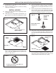
B. Place the air conditioner on the roof.
B. Measure (See FIGS. 9 & 10) the ceiling to roof thickness:
1. If distance is 25-50mm, remove perforated tabs from
both upper and lower ducts.
2. If distance is 50-75mm , remove perforated tabs from
bottom duct only.
3. If distance is 75-100mm, install ducts as received.
C. Check for correct alignment and adjust the unit as
necessary (Roof Gasket centers over 360mm x 360mm
opening).
D. Reach up into return air opening of the air conditioner and
pull the unit electrical cord down for later connection.
See FIG. 10.
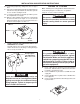
This unit weighs approximately 45 Kg. To
prevent back injury, use a mechanical hoist
to place air conditioner on roof.
CAUTION
FIG. 7
Recycle All
Cardboard
Lift And Place
Do Not Slide
FIG. 8
Front
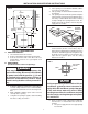
A. Remove the Air Conditioner from the carton and discard
the carton. See FIG. 7.
D. Place the Air Box Kit inside the RV. This box contains
mounting hardware for the air conditioner and will be
used inside the RV. See FIG. 7.
Do not slide the unit. This may damage the
neoprene gasket attached to the bottom and
create a leaky installation.
CAUTION
C. Lift and place the unit over the prepared opening using
the gasket as a guide. Seal under the gasket with silicon
sealant. The condenser coil goes toward
the rear of the RV. See FIG. 8.
FIG. 9
GASKET
CENTER A /C
FROM BEL OW
M
EASURE
C
EILING
T
HICKNESS
PULL DOW N
ELECTRICAL CORD
FIG. 10