Operating and Installation Instructions for CRAMER Glass Ceramic Gas Cooktop Model CC 05 GB GB CE-0085
Congratulations on your purchase of the Cramer gas glass ceramic cooktop CC05. You have chosen a cooking appliance that offers the convenience found in most modern-day households. A. O p e r a t i n g I n s t r u c t i o n s 1. Using the appliance 1.1 First-time use Before you use the appliance for the first time, make sure: - that the appliance has been installed by an authorized gas specialist with CORGI (Council for Registered Gas Installers) Registration.
Important: During initial startup and after replacing the gas cylinder, ignition may take longer than 15 seconds due to air in the gas lines. 1.2 Operation Important: the surfaces of the glass ceramic cooking zones become HOT during operation, even though no open flame is visible. Therefore, DO NOT ALLOW CHILDREN near the appliance! The appliance has two burners. The left burner is larger, with a diameter of 200 mm and a capacity of 1.8 kW. This burner is controlled by the knob in the back.
2.
d) "cera-fix" or "Collo profi" The choice of what to use depends on how dirty the cooktop is: a) Light spills that are not burned on can be wiped off with a damp cloth. b) Larger, dried-on spills can be easily removed with the razor blade scraper. c) Calcium and water deposits, grease and metallic discolorations can be cleaned with a suitable product, e.g. Sidol "Stahlglanz" or "Stahlfix" or "cera-fix" or "Collo profi". Important: All cleaning products must be wiped off completely with a wet cloth.
Keep the original packing material. Complaints can be processed only if the appliance is sent in the original package. B. Installation instructions 1. Important The appliance must be installed by an authorized technician registered by CORGI (Council for Registered Gas Installers). Output of the appliance (Hs) High setting: 1.8 kW (left burner) + 1.5 kW (right burner) Low setting: 1.3 kW (left burner) +1.
If the gas tap becomes sluggish or jammed, then it must either be replaced or the affected tap removed from the chamber, cleaned in benzine and lubricated with a special gas tap grease, e.g. type "Staburgas no. 32" from the Klüber company in Munich. This work must be carried out by a professional gas technician.
3. Connection of the appliance to the gas supply Only gas-tight fittings may be used for connecting the appliance to gas lines, in accordance with EN 1949. The pipes for connecting the appliance should be made of galvanized iron or of copper. These pipes must be used with a gas-tight fitting. After the connection has been established, the gas lines should be checked by applying a soap solution to the connecting points; any leaks can be detected by the formation of bubbles.
6. Visual check of flame The burners of the Cramer glass ceramic cooktop burn beneath the glass ceramic panel. Due to the dark shade of the panel, the ignited burner is not visible until approximately 1 minute after ignition. Due to a patented feature of the burner, only part of the burner surface is red hot, resulting in a pattern similar to a cake from which every other piece has been eaten. - The flame must burn steadily and with an even color.
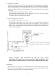
9. Mounting the appliance For the installation of the appliance, there must be a free space as indicated in Fig. 1 – 6, depending on the individual model (see type plate on appliance). The installation location is limited only as follows: there must be a distance of at least 400 mm between the cooktop and any furniture above (e.g. hanging cabinets). The appliance rests on the frame in the kitchen furniture.
Fig. 2 Exhaust gas and fresh air inlet flues, horizontal right rear (outside wall flue system, see Fig. 6) Truma flue pipe 80 Art.no. 39580-00 Cramer air inlet pipe 30 Cramer outside double flue Truma flue pipe 55 Art.no. 39320-00 Fig. 3 Exhaust gas and fresh air inlet flues, horizontal right side (outside wall flue system, see Fig. 6) Cramer outside double flue Truma flue pipe 55 Art.no. 39320-00 Truma flue pipe 80 Art.no.
Fig. 4 Exhaust gas and fresh air inlet flues, horizontal left side (outside wall flue system, see Fig. 6) Cramer outside double flue Truma flue pipe 80 Art.no. 39580-00 Cramer air inlet pipe 30 Truma flue pipe 55 Art.no. 39320-00 Fig. 5 Exhaust line, left vertical. Fresh air flue line, vertical from below through floor of vehicle Cramer air inlet pipe Cramer tube 30 Air outlet Air inlet Truma floor flue BK 24 Art.no. 39061-00 30 Truma roof flue Art.no. 30700-03 Truma flue pipe Art.no.
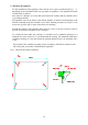
Fig. 6 Outside wall flue system The flue gas line through a flue pipe must never be installed at a slope. The maximum permissible length of the flue gas line is 2000 mm. The walls and elements located closer than 50 mm to the flue gas line must be covered or protected by materials of fireproof class M0 (see specified standards), e.g. TRUMA flue pipe ∅ 80, art. no. 39580-00 (see Fig. 6).
The air inlet line, made of flexible metal pipe with a diameter of 30 mm (Cramer), must be fastened at the air inlet of the appliance and at the Cramer outside double flue according to Figures 2, 3 and 4 with a worm drive hose clip, 25 – 40 mm ∅ (Cramer). 10. Do not install the appliance near highly flammable materials. 11. Removing the appliance from the furniture - Close main gas valve - Remove fastening screws - Disconnect gas connection and any electric cables 12.