
Installation guide


13
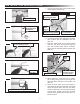
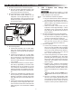
FIG. 21
Strip Jacket To 1″
FIG. 22
Hand Bend White
And Black Wires
Outward 90°
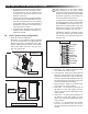
FIG. 23
Use Tip Of Pliers To Hold Wire In Place
While Hand Bending Wire At 90°
FIG. 24
Repeat With
Other Wire
FIG. 25
Trim Ground Wire To Length Of Outer Wires
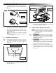
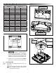
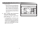
5. Hold the clear strain relief cover with the bottom
facing upward. See (FIG. 26).
FIG. 26
Load Cable into Strain Relief
Wire Locator
Slots
Position Black Wire
Into Locator Slot
Strain Relief Cover
(Bottom Facing Upward)
Strain
Relief
Fingers
Roll Cable Sheath Into
Integral Strain Relief
6. Lay wire into locator slots, making sure the black
wire is placed into the polarization slot. See
(FIG. 26).
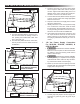
7. Press the cable sheath into the integral strain
relief slot. See (FIG. 26). Trimming of ground
wire and possibly others will be necessary.
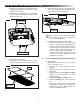
Wires must not extend beyond the locators. See
(FIG. 27).
FIG. 27
Housing Assembly
Hinge
Slots
Strain Relief Cover
Wires Trimmed And
Correctly Located
In Locator Stops
Hinge
Posts
8. While holding the strain relief cover, position
the housing's hinge posts into the hinge slots
and press down until both lock into place. See
(FIG. 27).
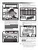
9. Close the strain relief cover and housing by
hand. Squeeze the top and bottom closed with
tongue and groove pliers. See (FIG. 28). Pliers
mustbeaminimumof10″long.Squeezermly
on both sides, squarely across the connector
between ribs A and B to ensure wires seat com-
pletely into slots.
INSTALLATION INSTRUCTIONS