CLIMATE CONTROL MARINE SELF-CONTAINED DCU, DLU, DTG, ECD, TX EN Self-Contained Air Conditioning System Installation manual.........................................................3 Form No.
Copyright © 2022 Dometic Group. The visual appearance of the contents of this manual is protected by copyright and design law. The underlying technical design and the products contained herein may be protected by design, patent or be patent pending. The trademarks mentioned in this manual belong to Dometic Sweden AB. All rights are reserved.
EN English 1 Important notes................................................................................................................................................. 3 2 Related documents.............................................................................................................................................3 3 Explanation of symbols and safety instructions........................................................................................................
EN Note Supplementary information for operating the product. 3.3 Supplemental directives To reduce the risk of accidents and injuries, please observe the following directives before proceeding to install this appliance: • Read and follow all safety information and instructions. • Read and understand these instructions before installing this product.
EN 4 Intended use This manual is intended for the installation of Turbo, Voyager, Vector Compact, EnviroCool, and Low Profile self-contained air conditioning systems (hereinafter referred to as air conditioner). This air conditioner is only suitable for the intended purpose and application in accordance with these instructions. This manual provides information that is necessary for proper installation of the air conditioner.
EN 4 Optional remote air sensor cable 12 Condensate drain hose barb 5 Seawater outlet hose 13 Mounting bracket 6 Overboard discharge 14 Air conditioner 7 Seawater inlet hose 15 Return air grille and filter 8 Seawater scoop thru-hull inlet 16 Insulated flexible ducting 6 Specifications This section contains specification data for the air conditioning unit. Table 1: Minimum duct and grille sizes per BTU capacity 3.
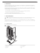
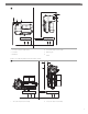
EN 2 1 2 1 2 3 3 5 5 4 6 4 6 1 3.0 in (3.00 cm) (3.0 in (76.0 mm)) 4 4.0 in (4.00 cm) (4.0 in (102.0 mm)) 2 Heat sink 5 Return air grille 3 Bulkhead 6 Airflow All other air conditioning units placement relative to airflow 3 4 5 2 3 1 4.0 in (4.00 cm) (4.0 in (102.0 mm)) 2 1 3 4 1 3.0 in (3.00 cm) (3.0 in (76.
EN 2 Return air grille 3 Airflow 5 Bulkhead Choose a location with sufficient airflow. The return air grille should have a minimum of 4.0 in (4.00 cm) (4.0 in (102.0 mm)) of air circulation clearance in front of it, free from any obstruction. If the air conditioner is positioned perpendicular to the return air grille, maintain a minimum of 3.0 in (3.00 cm) (3.0 in (76.0 mm)) air circulation clearance on the air intake side. Voyager only. Provide a minimum open area of 3.0 in (76.
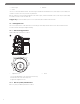
EN 5 1 2 3 1 Screw 2 Plate 3 Blower 1. Remove the seven screws on the plate. 2. Rotate the blower to the desired position. 3. Secure the blower in place using self-tapping screws(not provided). 7.2.3 Rotatable blowers Vector compact blower rotation 6 1 2 1 Screws on blower ring 2 Screws on drain pan or bracket 1. Remove the screws from the blower ring. 2. Remove the screws attaching the blower to the drain pan or bracket. 3. Rotate the blower to the desired position. 4.
EN 5. Plug any unused holes to prevent air loss. 7.3 Placing the air filters Air filters remove airborne particles from the cabin air and keep the evaporator coil clean. Place one air filter, either on the air conditioner or in the return air grille, for each air conditioner. 7.
EN Typical placement of mounting brackets and condensate drains 7 1 2 1 Condensate drain hose barb 2 Mounting bracket Condensate drain installation for Turbo and Voyager 8 4 3 2 5 1 1 Hose barb 4 Drain pan 2 Threaded drain hole 5 Drain hose 11
EN 3 Slug knockout Condensate drain installation for all other air conditioning units 9 5 4 3 2 1 1 Locking nut 4 Solid washer 2 Drain pan 5 PVC fitting 0.5 in (12.7 mm) HB x 0.5 in (12.7 mm) MPT) 3 Liquid-seal washer 1. Using the hose barb, knock out a slug from an a-facing drain hole by applying one quick strike with a rubber mallet. Discard the slug knockout. 2. For Turbo and Voyager units: a) Wrap the threaded end of the hose barb with plumbers tape.
EN 5. Route the drain hose downward to a safe and proper collection point.
EN 2 Fender washer (provided) Mounting bracket installation for other air conditioning units a 1 3 2 14 1 Drain pan 2 Mounting bracket 3 Mounting bolt (not provided)
EN 6. Install one mounting bracket on each side of the drain pan, evenly spaced. Installing foam handle insulation on Voyager units b 3 2 1 1 Foam handle insulation 2 Handle opening 3 Drain pan 7. For Voyager units: a) Remove the film covering the adhesive backing on the foam handle insulation. b) Position the foam handle insulation to completely cover the handle opening with the adhesive side facing the drain pan.
EN Ducting connections c 2 1 3 4 5 1 Fiberglass insulation 4 Inner mylar duct hose 2 Mount ring 5 Duct tape 3 Transition box 1. Slide the inner mylar duct hose around the mount ring to the transition box. 2. Screw three or four stainless steel screws through the mylar duct hose into the mount ring, capturing two or three wires with screw heads. 3. Slide the fiberglass insulation around the inner mylar duct hose to the transition box. Secure with duct tape. 8.
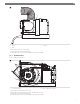
EN Seawater system d 3 2 1 11 10 7 8 4 6 9 5 1 Seawater outlet 7 Uphill inlet flow 2 Outlet flow 8 Ball valve 3 Air conditioner 9 Scoop thru-hull inlet 4 Seawater pump 10 Water line 5 Hose clamps 11 Correct pump head strainer orientations 6 Strainer 1. Install a seawater scoop thru-hull inlet as close to the keel and as far below the water line as possible. Secure the scoop thruhull inlet using a marine-grade sealant designed for underwater use. 2.
EN • Alternating current (AC) grounding must be connected to the ground terminal (GRND) at the AC power input terminal block. • Connections between the vessel’s AC system grounding conductor and the vessel’s direct current (DC) negative or bonding system should be made as part of the vessel’s wiring. When maintenance or replacing existing equipment that contains a chassis- mounted ground stud, check the vessel’s wiring for these connections.
EN All other regions The statutory warranty period applies. If the product is defective, please contact the manufacturer’s branch in your region or your retailer (see the back of this instruction manual for the web addresses to locate your region or retailer).
339708 L-4111 2022-12-15