
Instruction Manual
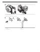
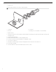
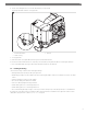
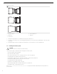
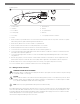

Table Of Contents

EN
Seawater system -
d
1
2
3
4
6
10
11
8
9
7
5
1 Seawater outlet 7 Uphill inlet flow
2 Outlet flow 8 Ball valve
3 Air conditioner 9 Scoop thru-hull inlet
4 Seawater pump 10 Water line
5 Hose clamps 11 Correct pump head strainer orientations
6 Strainer
1. Install a seawater scoop thru-hull inlet as close to the keel and as far below the water line as possible. Secure the scoop thru-
hull inlet using a marine-grade sealant designed for underwater use.
2. Install a bronze, full-flow seacock on the seawater scoop thru-hull inlet.
3. Install a seawater strainer below the level of the pump with access to the filter.
4. Mount the pump above the strainer and at least one foot below the waterline.
5. Connect the seacock and strainer with an uphill run of reinforced marine-grade hose.
6. Connect the discharge from the pump uphill to the bottom inlet of the air conditioners condenser coil with a 5/8 in (0.6 in
(16.0 mm)) reinforced, marine-grade hose.
7. Connect the discharge from the condenser coil to the overboard discharge thru-hull fitting with a 5/8 in. reinforced ma-
rine-grade hose.
8. Avoid loops, high spots, or the use of 90.00 ° elbows with the seawater hose. Each 90.00 ° elbow is equivalent to 2.5
(29.9 in (76.00 cm)) of hose and a 90° elbow on the pump outlet is equivalent to 20.0 (240.2 in (610.00 cm)) of hose.
9. Double-clamp all hose connections using two stainless steel clamps, reversing the clamps where necessary.
10. Connect all metallic parts in contact with seawater to the vessel’s bonding system.
8.4 Making electrical connections
WARNING! ELECTRICAL SHOCK HAZARD.
Always turn off the air conditioning power supply breaker before opening the electrical box. Failure to obey this warning
could result in death or serious injury.
NOTICE!
The air conditioner must be connected to the boat’s bonding system to prevent corrosion due to stray electrical current.
All pumps, metallic valves, and fittings in the seawater circuit that are isolated from the air conditioner by PVC or rubber
hoses, must be individually bonded to the boat’s bonding system.
Note Failure to properly ground and bond the system will void the warranty.
All conditioning units have a terminal strip, labeled for proper connections, inside the electric box. The wiring diagram inside the
electric box supersedes ABYC standards. Use the correct size circuit breaker to protect the system as specified by the air condi-
tioning units data plate label. A minimum of 12 AWG boat cable should be used to supply power to the air conditioner and the
seawater pump. Make all connections using ring or captive fork terminals.
Observe the following when making electrical connections:
17