
Instruction Manual

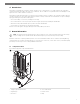
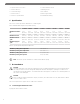
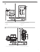
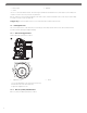
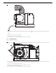
Table Of Contents

EN
4 Optional remote air sensor cable 12 Condensate drain hose barb
5 Seawater outlet hose 13 Mounting bracket
6 Overboard discharge 14 Air conditioner
7 Seawater inlet hose 15 Return air grille and filter
8 Seawater scoop thru-hull inlet 16 Insulated flexible ducting
6 Specifications
This section contains specification data for the air conditioning unit.
Table 1: Minimum duct and grille sizes per BTU capacity
3.5 k BTU 6 k BTU 8 k BTU 10 k BTU 12 k BTU 16 k BTU 18 k BTU 27 k BTU
Minimum duct diame-
ter
3.0 in
(76.0 mm)
4.0 in
(102.0 mm)
5.0 in
(127.0 mm)
6.0 in
(152.0 mm)
6.0 in
(152.0 mm)
7.0 in
(178.0 mm)
7.0 in
(178.0 mm)
8.0 in
(203.0 mm)
Minimum duct area
2.6 in²
(17.0 cm²)
5.0 in²
(32.0 cm²)
7.7 in²
(50.0 cm²)
11.2 in²
(72.0 cm²)
11.2 in²
(72.0 cm²)
15.2 in²
(98.0 cm²)
15.2 in²
(98.0 cm²)
19.8 in²
(128.0 cm²)
Minimum return air
grille
25.3 in²
(163.0 cm²)
25.3 in²
(163.0 cm²)
31.5 in²
(203.0 cm²)
39.4 in²
(254.0 cm²)
51.1 in²
(330.0 cm²)
78.7 in²
(508.0 cm²)
78.7 in²
(508.0 cm²)
94.5 in²
(610.0 cm²)
Minimum supply air
grille
4.6 in²
(30.0 cm²)
12.6 in²
(81.0 cm²)
18.9 in²
(122.0 cm²)
23.6 in²
(152.0 cm²)
27.6 in²
(178.0 cm²)
31.5 in²
(203.0 cm²)
39.4 in²
(254.0 cm²)
55.2 in²
(356.0 cm²)
Table 2: Operating water temperature and pressure
Minimum operating water temperature 39.2 °F (4.00 °C)
Maximum operating water temperature 80.6 °F (27.00 °C)
Minimum operating water pressure 4.2 psi (29.00 kPa)
Maximum operating water pressure 6.00 psi (41.4 kPa)
Note The unit can operate outside these conditions with reduced capacity.
7 Pre-installation
NOTICE!
The Turbo and Voyager self-contained condensate base pans are equipped with vibration isolators installed in the bot-
tom of the pan. These isolators are designed to dampen the vibration caused by the operating air conditioner from
transferring into the mounted surface. Care must be taken when moving the air conditioner across mounting surfaces as
the isolators can be damaged.
NOTICE!
The air conditioner must be mounted to a low, flat, level surface, like in the bottom of a locker, under a bunk or dinette
seat, or in a similar location.
This section explains how to prepare the air conditioner for installation.
7.1 Determining the installation location
Voyager placement relative to airflow -
6