RM2351 RM2354 RM2451 RM2454 RM2551 RM2554 DM2652 DM2662 DM2663 DM2852 DM2862 DM3862 NDM1062 NDR1292 FOR YOUR SAFETY If you smell gas: 1. Open windows. 2. Don’t touch electrical switches. 3. Extinguish any open flame. 4. Immediately call your gas supplier. FOR YOUR SAFETY Do not store or use gasoline or other flammable vapors and liquids in the vicinity of this or any other appliance. ! WARNING USA Service Office Dometic, LLC 2320 Industrial Pkwy.
INTRODUCTION Thank you for entrusting us to supply your new quality-guaranteed refrigerator. It is to be used as a recreational device designed for storage of foods, frozen foods and making ice. Please, when the refrigerator is not in use as a recreational device, turn the system off and open the door(s).
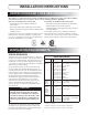
INSTALLATION INSTRUCTIONS CERTIFICATION AND CODE REQUIREMENTS This appliance is certified under the latest edition of ANSI Z21.19•CSA 1.4 Refrigerators using gas fuel. The installation must conform with local codes, or in absence of local codes, the following standards as applicable. In the U.S. the installation must conform with: In CANADA, the installation must conform with: • Natural Gas and Propane Installation Code, CSA B149.1 • National Fuel Gas Code, ANSI Z223.1/NFPA 54 (latest edition).
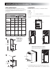
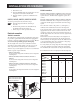
VENTILATION REQUIREMENTS VENTILATION HEIGHTS CLEARANCES It is essential that all maximum or minimum dimensions are strictly maintained, as the performance of the refrigerator is dependent on adequate flow of air over the rear of the refrigerator.
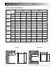
VENTILATION REQUIREMENTS OVERALL AND RECESS DIMENSIONS Dimensions Model Overall Recess Height A Width B Depth C Height H Width W Depth D RM2351 RM2354 inches 30-5/32 21-7/8 22-22/32 29-3/4 20-1/2 21-3/8 mm 766 556 577 756 521 542 RM2451 RM2454 inches 37-3/8 24-7/8 24-11/16 39-9/16 23-11/16 24 mm 948 632 627 928 602 610 RM2551 RM2554 inches 43-1/2 24-7/8 24-11/16 42-5/8 23-11/16 24 mm 1104 632 627 1083 602 610 DM2652 DM2662 DM2663 inches 54-21/32 24-7/
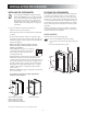
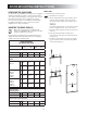
INSTALLATION PROCEDURE INSTALLING THE REFRIGERATOR SECURING THE REFRIGERATOR • Make sure the floor is solid and level. It is important to follow the sequence in securing refrigerator in enclosure since failure in doing so can cause leakage between the frame and cabinet. Any space between the counter, storage area or ceiling and top of the refrigerator greater than 1 1/2 inches should be blocked.
INSTALLATION PROCEDURE 3. One screw installed in the rear base. RM2451, RM2454, RM2551, RM2554, DM2652, DM2662, DM2663, DM2852, DM2862, DM3862 & NDM1062 Install the screws in the following order: 1. Two screws installed through the front base. (Installation of the lower front strip.) The refrigerator is provided with a lower front strip (shipped as a loose part). Attach the front strip after the refrigerator is set into the cutout opening.
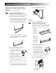
INSTALLATION PROCEDURE DRAIN WATER HOSE Drill a hole through flooring. To avoid damage to the hose, the hole must be positioned so that the hose doesn’t touch the boiler casing. Seal around the hose that goes through the drilled hole and ensure that it does not kink when run through the floor. Check to make sure that the supplied hose is long enough in order for the water to drain outside of the vehicle. If not, the installer will have to supply the extra length of hose.
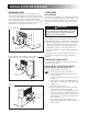
INSTALLATION PROCEDURE 9. Put back the cover. 10. Press the ON/OFF button off and then back on. Normal operation of the burner should return. 11. Allow the burner to operate for a minimum of five minutes. 12V DC connection RM2451, RM2551, DM2652 & DM2852: These refrigerator models are not designed for 12V DC operation of the cooling system. However, 12V DC must be supplied to operate the controls.
DOOR MOUNTING INSTRUCTIONS REVERSING THE DOOR SWING With screws For all models, except NDR1292, the refrigerators are equipped with hinges that makes it possible to change the direction the door opens by moving the hinges to the opposite side. A special hinge kit must be used in order to change the door swing. For conversion kit number, see APPENDIX A - SPARE PARTS. For additional information, please contact service point or distributor service dept. for assistance.
DOOR MOUNTING INSTRUCTIONS Snap in 1 To mount the panel, follow these steps: 1. Open the door 90 degrees. 2. On new refrigerators, the decoration strip are taped inside the door; if installed on the door, remove the door decoration strip (2) by gently pushing the four tabs away with a flat blade screwdriver (1). 3. Insert the vertical edges into the grooves of the door frame (3). 4. Push the panel downwards so that the lower horizontal edge of the panel (4) is fitted into the bottom grove (5). 5.
OPERATING INSTRUCTIONS REFRIGERATOR OVERVIEW ABSORPTION COOLING SYSTEM MODES OF OPERATION In an absorption refrigerator system, ammonia is liquefied in the finned condenser coil at the top rear of the refrigerator. The liquid ammonia then flows into the evaporator (inside the freezer section) and is exposed to a circulating flow of hydrogen gas, which causes the ammonia to evaporate, creating a cold condition in the freezer.
REFRIGERATOR OVERVIEW DC mode CLIMATE CONTROL SYSTEM RM2354, RM2454, RM2554 & DM2663 DM2652, DM2662, DM2663, DM2852, DM2862, DM3862, NDM1062 & NDR1292 When operating in DC mode (3-way models only), the DC mode indicator lamp is illuminated and all other lamps are off. To select another operating mode, turn off the DC mode by pressing the DC selector button. The DC lamp is turned off.
REFRIGERATOR OVERVIEW RM2354, RM2454, RM2554 & DM2663 A D E ON DC AUTO 1 2 3 OFF AC GAS B COLD 1 3 2 4 5 COLDEST 4 CHECK C F 1. 2. 3. 4. ON/OFF button (main power) DC mode selector button AUTO/GAS mode selector button Temperature selector button DC mode indicator lamp AC mode indicator lamp GAS mode indicator lamp AUTO mode indicator lamp CHECK indicator lamp (GAS mode only) F. Temperature indicator lamps A. B. C. D. E. DM2662, DM2862 & NDM1062 A 1. ON/OFF button (main power) 2.
INSTRUCTIONS FOR USE To turn off STARTUP The refrigerator may be shut off while in any mode of operation by pressing the main power ON/OFF button to the OFF position. This shuts off all DC power to the refrigerator, including the interior light. If the refrigerator will not be in operation for a period of weeks, it should be emptied, defrosted, cleaned and the doors left ajar. The ice trays should also be dried and kept outside the cabinet. ! WARNING 6 FIRE HAZARD.
INSTRUCTIONS FOR USE The following information, “USING THE ICE MAKER”, is only valid for refrigerator model NDM1062 equipped with ice maker. USING THE ICE MAKER How it works Before the ice maker can operate, make sure that the: • Refrigerator is connected to 120 V AC. • Water valve supplying the refrigerator is turned on. • Ice level bail arm is in its fully down position.
STORAGE COMPARTMENTS REFRIGERATOR VOLUME MODEL FROZEN FOOD STORAGE COMPARTMENT This compartment is not designed for deep or quick freezing of food. • To prevent food from drying out, keep it in covered dishes, containers, plastic bags or wrapped in aluminum foil. • Meat or fish, whether raw or prepared, can be stored in the frozen food storage compartment provided they are precooled first in the refrigerator.
STORAGE COMPARTMENTS REMOVING AND REPLACING THE SHELVES 2 1 Slide the wire shelf to the left. The right-hand side of the shelf will come loose. Put a screwdriver into the slot of the shelf lock. Turn the screwdriver counter clockwise. Remove the shelf locks from the wire shelf. 3 4 Lower the right-hand side of the wire shelf and let the left-hand side slide out of the holes in the wall. Insert the ends of the wire shelf on the left-hand side at the desired position.
PRODUCT CARE DEFROSTING Draining the ice maker 1. Shut off the refrigerator by pressing the main power ON/OFF button (OFF position). If the RV is in storage and the refrigerator or the DC power is turned “OFF” there will be no 12V DC present to operate the heat tape; therefore, it will be necessary to drain and dry the ice maker. This will prevent water from freezing in the solenoid valve or becoming stale and producing bad tasting ice.
PRODUCT CARE 9. Turn the gear counterclockwise, when the hold switch closes, the mold assembly will continue to operate through the harvest cycle. During the water fill sequence of the harvest cycle the compressed air will blow out the water trapped in the solenoid valve. 10. Repeat the harvest cycle operation several times. Up to 20 PSIG air pressure can be used to clear the solenoid valve. Damage to solenoid can occur if AC power is applied for more than 20 seconds. 11.
MAINTENANCE & SERVICE ! CAUTION 6 To keep the refrigerator working properly, a qualified service technician should, at least once a year, inspect the connections, the control system, the LP gas pressure and flue baffle. The service and maintenance described in this section is to be performed by service personnel only! ELECTRIC EQUIPMENT Heater If your refrigerator stops cooling, immediately turn the refrigerator off and see a Dometic dealer.
MAINTENANCE & SERVICE 5. Remove the wire and flue baffle from the top of the flue tube. 6. Using a flue brush, clean the flue from the top. Blowing compressed air into the flue will not properly clean soot and scale out of the flue tube. 7. Put back the flue baffle. 8. Clean the burner tube with a brush. Blow out the burner with compressed air. PERIODIC MAINTENANCE Checking the control system Check the control system by connecting/disconnecting the 120V AC power, starting/stopping the engine, etc.
TROUBLESHOOTING If you run into a problem, refer to the troubleshooting table below. Symptom Check/Remedial action The refrigerator has stopped cooling. • Immediately turn the refrigerator off and see a Dometic dealer. Refrigerator or freezer is not cold enough • Is the plug firmly connected to the socket? Is the socket switched on? Check the socket by plugging in another appliance. • Defective fuse? Fit a new fuse. • For refrigerators equipped with thermostat - check if it is properly set.
APPENDIX A - SPARE PARTS The following table displays commonly used parts which should be available from your Dometic Service Center. MODEL RM2351 RM2354 RM2451 RM2454 RM2551 RM2554 DM2652 N.A. N.A. N.A. N.A. N.A. N.A. 3850781-01 2007172-02/2 2007172-02/2 2932667-01/3 2932667-01/3 2932667-02/1 2932667-02/1 2932667-03/9 SPARE PARTS Airing position card Baffle Bottle holder, 2 pieces N.A. N.A. N.A. N.A. N.A. N.A. N.A. 2932636-01/8 2932636-01/8 N.A. N.A. N.A. N.A. N.A.
APPENDIX A - SPARE PARTS MODEL DM2662 DM2663 DM2852 DM2862 DM3862 NDM1062 NDR1292 SPARE PARTS Airing position card Baffle Bottle holder, 2 pieces Box 3850781-01 3850781-01 3850781-01 3850781-01 N.A. N.A. N.A. 2932667-03/9 2932667-03/9 2932667-04/7 2932667-04/7 2932667-04/7 2932667-04/7 2932667-05/4 N.A. N.A. N.A. N.A. N.A. N.A. 2932658-01/2 N.A. N.A. N.A. N.A. N.A. N.A. N.A. 2932621-07/7 2932621-07/7 2932621-01/0 2932621-07/7 2932621-09/3 N.A. N.A.
APPENDIX B - CONSUMER SUPPORT Dometic website www.dometicusa.com Please visit the website for information and news about Dometic products. You can obtain information about how to get in contact, learn about product care, download manuals, leaflets and warranties. Service and spare parts For service, please contact the Service Center Assistance, see the front page of this manual - or - visit the Dometic website to find the location of the nearest Dometic Service Center.
APPENDIX C - DOMETIC WARRANTY & MAINTENANCE SCHEDULE IMPORTANT! Valuable Dometic Refrigerator Warranty & Maintenance Schedule Congratulations, and Thank You for purchasing the industry’s best built and best backed RV Refrigerator. Enclosed you will find important warranty and maintenance information on Dometic’s exclusive three (3) year warranty. Please take a few moments and familiarize yourself with the program.
LIMITED THREE-YEAR WARRANTY DOMETIC REFRIGERATORS THE SELLER NAMED BELOW MAKES THE FOLLOWING WARRANTY WITH RESPECT TO THE DOMETIC PRODUCT: 1. This warranty is made only to the first purchaser (herein after referred to as the “Original Purchaser”) who acquires the product for his own use and is installed and operated within the continental United States and Canada. 2.
REFRIGERATOR OWNER MAINTENANCE YEARLY RECORD #USTOMER .AME !DDRESS #ITY 0HONE -ODEL .O 3ERIAL .O 3TATE $ATE OF 0URCHASE :IP #ODE 3%#/.
APPENDIX D - REARVIEW EQUIPMENT RM2351 Heater Flue baffle Drain water hose Power module cover Protection cover Screw for protection cover Burner jet 12 V DC Terminal block Manual gas shutoff valve Inlet fitting Flexible cord RM2354 Heaters Relay Flue baffle Drain water hose Power module cover Protection cover Screw for protection cover Burner jet 12 V DC Terminal block Manual gas shutoff valve Inlet fitting Flexible cord - 30 -
APPENDIX D - REARVIEW EQUIPMENT RM2451, RM2454, RM2551 & RM2554 Heater Relay, 3-way only Flue baffle Power module cover Protection cover 12V DC Screw for protection cover Burner jet 12 volt Terminal block Manual gas shutoff valve Inlet fitting Flexible cord Drain water hose DM2652, DM2662, DM2663, DM2852, DM2862, DM3862 & NDM1062 Heater(s) Relay, 3-Way only Thermofuse Flue baffle Power module cover Protection cover 12V DC Screw for protection cover 12 volt DC Terminal block Burner jet Flexible
APPENDIX D - REARVIEW EQUIPMENT NDM1062 (WITH ICE MAKER) Heater Relay Thermofuse Power module cover Flue baffle Protection cover 12V DC Flexible cord Manual gas shutoff valve Flexible cord (Ice maker) 12V DC Terminal block Burner jet Thermostat Inlet fitting Drain water hose NDR1292 Heaters Power module cover Thermofuse Flue baffle 12V DC Protection cover Burner jet Manual gas shutoff valve 12 volt Terminal block Inlet fitting - 32 - Drain water hose Flexible cord
APPENDIX E - WIRING DIAGRAMS RM2351, RM2451 & RM2551 RM2354, RM2454 & RM2554 - 33 -
APPENDIX E - WIRING DIAGRAMS DM2652, DM2662, DM2852 & DM2862 385 13 98 T GREEN ORANGE BLUE RED BROWN BLACK 9 P2ï1 P2ï2 3 3 J6 J4 K J5 GROUND L N 9 E J2 +12V 4 8 C B J8 9 P3ï4 P3ï3 P3ï2 P3ï1 A J10 M P1ï1 P1ï4 P1ï2 P1ï5 P1ï6 P1ï3 J7 D N 3A J4 R J6 J5 J7 5A J2 3 P2 1234 123456 12 3 J J10 P1 J 1 1 J8 P3 1 1 U 1 1 F H 1 9 P 5 S L 6 T L G M DISPLAY BOARD 12V DC E PROTECTIVE EARTH SWITCH CHASSIS GROUND TEST POINT THERMAL FUSE P CIRCUIT BOARD POW
APPENDIX E - WIRING DIAGRAMS DM2663 385 13 99 9 A O 9 3 3 J W 1 J10 J7 3 J5 3 J6 C J4 L 1 1 J6 J5 J2 30 K B N 3A 86 7 4 P2ï1 P2ï2 GROUND J4 7 P3ï4 P3ï3 P3ï2 P3ï1 J8 9 P1ï1 P1ï4 P1ï2 P1ï5 P1ï6 P1ï3 J2 N L 87 P GREEN ORANGE BLUE RED BROWN BLACK +12V 85 X D T J7 5A J8 1 3 P3 P1 P2 123456 12 Y 1 F H X 1 9 1 S 5 U M 6 N DISPLAY BOARD L G E 3 3 K J10 1234 8 1 R N 12V DC E Y A J C 87 85 CIRCUIT BOARD POWER FUSE 3A FUSE 5A CIRC
APPENDIX E - WIRING DIAGRAMS NDM1062 MODEL EQUIPPED WITH STAINLESS STEEL DOORS 385 14 04 D T GREEN ORANGE BLUE RED BROWN BLACK O 9 E 8 J5 J10 C B J4 3 4 P2ï1 P2ï2 J2 3 1 8 9 1 J8 9 P3ï4 P3ï3 P3ï2 P3ï1 A J7 L P1ï1 P1ï4 P1ï2 P1ï5 P1ï6 P1ï3 J6 +12V LAC GND CLC J M N 3 3 +12V 3 1 GROUND L N 3A J4 V 3 J6 5A J2 H Y P1 P2 123456 12 U H J10 P3 9 1 8 G F L R 6 P N L A +12V LAC GND CLC B C D E F M G H E J K J L N M N G F O P U S K 12V DC DISP
APPENDIX E - WIRING DIAGRAMS NDM1062 MODEL EQUIPPED WITH DOOR INSERT PANELS 385 14 05 Z GREEN ORANGE BLUE RED BROWN BLACK 9 E J10 J5 J4 J2 J M GROUND L N T J6 J5 3 1 J7 5A J2 1 J8 P3 P1 P2 123456 12 1 R H 9 1 S 5 L X K 6 P N 12V DC L S CIRCUIT BOARD POWER FUSE 3A FUSE 5A CIRCUIT BOARD DISPLAY ELECTRODE LAMP SWITCH LAMP HEATER 120V AC HEATING CABLE TERMINAL BLOCK THERMISTOR THERMOFUSE FANS SOLENOID VALVE RETAINER THERMAL FUSE B E C D E F F M G H U J K L J R G
APPENDIX E - WIRING DIAGRAMS NDR1292 MODEL EQUIPPED WITH STAINLESS STEEL DOORS 1 D GREEN ORANGE BLUE RED BROWN BLACK 1 +12V L 3A J10 J7 J2 3 3 3 1 1 3 V 1 1 1 J7 5A J2 FAN 3 J6 J5 FAN P C B GROUND N J4 E P2ï1 P2ï2 1 J5 8 3 3 9 9 8 J6 9 4 P3ï4 P3ï3 P3ï2 P3ï1 A J8 L P1ï1 P1ï4 P1ï2 P1ï5 P1ï6 P1ï3 J4 J M T +12V LAC GND CLC 385 13 30 3 J8 H H J10 P1 P3 1234 U 123456 1 8 P2 R K 5 S G F 12 9 L N 6 N 12V DC T L DISPLAY BOARD A CIRCUIT BOARD
PROTECTION FOR YOUR NEW INVESTMENT We truly appreciate that you have chosen to purchase a Dometic product for your recreational vehicle and we want to help you protect this wise investment. We at Dometic back our products with one of the most comprehensive warranties in the industry. Complete the registration card below and mail to us or register your Product on-line at www.edometic.com.
Ŷ Ŷ WARRANTY VERIFICATION Your prompt registration records your right to protection under the terms and conditions of your warranty. Ŷ Your completed Owner’s registration card serves as confirmation of ownership in the event of product damage or theft. Ŷ FACTORY COMMUNICATION OWNER CONFIRMATION Returning your card of registering on-line guarantees you will receive product information and specials. Leaving your email address below will allow us to communicate with you quickly and efficiently.