
Troubleshooting guide

INSTALLATION PROCEDURES Eskimo Ice Installation & Operation Manual
6 L-3040 ENGLISH
INSTALLATION PROCEDURES
This section covers the installation procedures for your ice-making system. Read the manual completely before attempting
to install any equipment.
CHOOSING THE CORRECT EQUIPMENT VOLTAGE
Know the frequency and voltage provided where your ice-making system will be used and select the appropriate 60 Hz or 50 Hz
model. Do not operate a 60Hz unit on 50Hz power or a 50Hz unit on 60Hz power, as this will cause damage and void the
warranty.
The voltage rating of a unit is a nominal rating. The voltage in a given location may be higher or lower by as much as 10% and
the system will still operate correctly. For example, in a 60 Hz environment you may see 110 VAC to 120 VAC, or 208 VAC to
240 VAC. In a 50 Hz environment common voltages range from 220 VAC to 240 VAC.
INSTALLING THE UNIT
SELECTING THE SITE
Never install the unit in the bow of the boat. Dometic ice-making units are designed to be installed in any convenient location
on the transom, in the aft, or in a machinery space that does not require ignition protection that is as far aft of midship as
possible. The unit can be located in living areas if necessary. Some considerations:
• This equipment is not ignition protected per CFR 183.410 and may not be installed in areas that may be
exposed to flammable gas.
• The unit will produce condensation, so the drip pan is necessary.
• The unit is water cooled and does not need direct ventallation, but do not install in a sealed space.
• The space around the unit may be insulated to reduce noise if necessary.
Site Location Check List
• Location is aft of midship. Never install the unit in the bow of the boat.
• Location is not exposed to flammable gas.
• Location provides adequate space for access to refrigerant, seawater, and electrical connections.
• Location provides accessibility for service and maintenance.
• Location is away from direct spray, from engine air intakes, and from water washdown.
• Mounting space is a flat, horizontal surface.
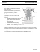
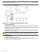
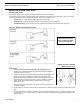
MOUNTING THE UNIT
1. Do not remove any covers, caps, or fittings that may expose any wiring or refrigerant until you are ready for those
steps of the installation.
2. On a flat, horizontal surface, orient the unit so the refrigerant, seawater, and electrical connections are accessible and
use the 4 provided hold-down clips to secure it.
3. If you decide to remotely mount the control box, be sure it is away from direct spray, from engine air intakes, and from
water washdown.
4. If pump wires need to be extended by butt connections, make sure they are tightly crimped and heat shrunk.
5. AC power source must be installed and grounded/bonded in accordance with ABYC standards.
6. Connect control wires to terminal strip with ring terminals.
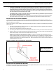
INSTALLING CONDENSATE DRAINAGE
The condensate drain pan is 2.0” (51mm) high with one drain location. During conditions of high humidity, condensate may be
produced at a rate of approximately one-half gallon (1.9 liter) per hour. With this in mind, it is important to route condensate
drains downward to a sump pump. It is not recommended to route condensate drains to the bilge.
After the condensate drain installation is complete, test the installation by pouring one quart (liter) of water into the pan and
checking for good flow.