HB 2500 HEAT PUMP Operation, maintenance and installation manual Libretto istruzioni per l’uso, la manutenzione e l’installazione Betriebs-, Wartungs- und Installationsanleitung Manuel d’utilisation, d’entretien et d’installation Bedienings-, onderhouds- en installatiehandleiding Manual de instrucciones para el uso, mantenimiento e instalación Manual de instruções de uso, manutenção e instalação Handbok för användning, underhåll och installation Käyttö-, huolto- ja asennusohje Bruks- vedlikeholds- og insta
ENGLISH With Dometic at home everywhere. Thank you for your decision to buy an Dometic product. They all have been specially conceived for your vehicle, matching totally the requirements of leisure on wheels - with more than 75 years of experience, the most advanced technology, first-rate materials, superb workmanship, functional design and a care for the environment.
©DOMETIC - 2007 All rights reserved - Printed in Italy No part of this manual may be duplicated, copied or published in any form without written authorization from DOMETIC The figures, descriptions, references and technical data contained in this manual are merely guidelines and are not binding. DOMETIC reserves the right to make all the modifications it may deem fit, at any time and without notice, in a constant effort to improve quality and safety, without undertaking to update this manual each time.
Validity of warranty “The Product is guaranteed in accordance with the law and regulations made after assimilation of Directive 1999/44/EC.” The manufacturer’s warranty is expressly excluded in the event of breakage and/or abnormal operation of the Product caused by and/or depending on incorrect assembly. It is the Consumer’s right to have the Product fitted by authorized dealers that are not subordinate to Dometic.
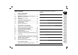
Table of Contents Instructions handbook for operation, maintenance and installation Heat pump 1 General information 1.1. 1.2. 1.3. 1.4. 1.5. 1.6. 1.7. 1.8. 1.9. Scope of the manual.............................................4 Manufacturer and machine identification......4 Machine description...........................4 User tips................................................6 Description of controls..................................6 Installing and changing batteries......................
1 General information 1.1. Scope of the manual GB 1.3. Machine description This manual has been drawn up by the Manufacturer and is an integral part of the machine. The information it contains, if observed, can guarantee correct use of the machine. The first part of the manual is for the user , while the second part is for the expert personnel who install the machine. This machine has been designed and built to be installed on vehicles (motor homes, caravans, special vehicles, etc.
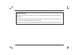
General information 4-way switchover valve (F) 1 Condenser (B) GB Fan (C) Heating element Evaporator (D) Compressor (A) Remote panel flow of air drawn from inside the vehicle Flow of ia r int rodu ced from the outs ide hot air expelled treated air reintroduced inside the vehicle condensation drain in heat pump condensation drain Operating instructions for users 5 HB2500
1 General information GB 1.4. User tips cold mode The machine performance can be improved by taking some precautions. ventilation mode automatic mode • Improve the vehicle’s heat insulation by eliminating openings and covering the glass surface with reflecting curtains. • Avoid frequently opening doors and windows when not necessary. • Select the appropriate temperature and fan speed. Direct the air vents suitably.
General information TABLE A Automatic mode 1 note1: note2: 1 Press the on/off button to switch on the machine. Internal temperature T≤20°C 20°C
1 General information GB Dehumidification mode HB2500 Ventilation mode 1 Press the on/off button to switch on the machine. 1 Press the on/off button to switch on the machine. 2 Press the change mode button to select dehumidification mode. 2 Press the change mode button to select ventilation mode. 3 Press the selection buttons to set the ambient temperature on the desired value between 18°C and 30°C.
General information Heat pump mode 1 Night mode GB 1 Press the on/off button to switch on the machine. 1 Press the on/off button to switch on the machine. 2 Press the change mode button to select heat pump mode. 2 Press the change mode button to select the desired mode from all the ones available. 3 Press the selection buttons to set the ambient temperature on the desired value between 18°C and 30°C. 3 Press the night mode button to turn this function on and off.
1 General information GB Timer off mode 1 Press the on/off button to switch on the machine. 1 The machine must be off. 2 Press the change mode button to select the desired mode from all the ones available. 2 Press the timer on button to set the time when the machine must switch on4. 3 Press the selection buttons to set the ambient temperature on the desired value between 18°C and 30°C. 3 Press the selection buttons to change the time when the machine must switch on.
General information 1.6. Installing and changing the remote control batteries 1.7. Description of the receiver GB The receiver panel is composed of a display and four LEDs of different colours. The display switches on whenever it receives pulses from the remote control to display the temperature setting; after a few moments the ambient temperature is displayed and then it switches off. The four LEDs signal the machine’s functional status. The red LED signals power on.
1 General information 1.8. Technical data 280 153 57 27 30 GB 710 400 Description Refrigerant type/quantity Refrigerating capacity Heating capacity Consumption when cooling Consumption when heating Breakaway current Additional heating element Electricity supply Protection class Treated volume of air (max) Max volume (recommended with insulated walls) Weight E.E.R. C.O.P.
General information 1 1.9. Routine maintenance GB Petrol Cleaning; do it periodically, removing the dust with a moist cloth. If necessary, use a non-aggressive detergent. Never use petrol or solvents. Checking: Do it periodically, making sure that: - the condensation drain holes are not obstructed. - the openings in the floor are not obstructed. Filters cleaning (1): periodically carry out this operation; wash the filters (N.1) with a detergent solution and allow to dry before refitting.
1 General information GB Installation can be performed by persons with specific technical knowledge. In addition to this requirement, installers must have adequate working conditions in order to ensure their own safety and that of others. 2.1. Packing, unpacking and handling Observe the instructions given on the packing. Lift the machine, checking it is sound. Lift it using the handles or the belts on the base. Transfer the machine to the place of installation in conditions of safety.
Information on installation 2 2.2. Choice of the place of installation GB To accomplish uniform climate control in a vehicle, the machine must be installed as near the middle as possible, in a housing or a similar device. Position the machine so as to ensure easy access for servicing and to facilitate disassembly and installation. Place the assembly template in the compartment intended for installation and check the space available for the openings in the floor.
2 Information on installation 2.3. Preparing the opening and fixing 30m m 710 m 30m 87 141.5 609 280 193 33 65.5 Ø 20 Ø 55 207,5 267.5 16 400 GB 123 187 200m m To install the machine it is necessary to create openings in the floor. The openings in the floor of the vehicle must be accessible and, therefore, must not be covered by parts of the chassis frame behind or the like. These openings must not be reached by splashes from the wheels; fit a splash guard or something similar if necessary.
Information on installation 2 2.3.1 Fixing systems GB Parts supplied for the a/c fixing Mode 1: use n° 4 screws for the a/c fixing x2 x8 (system 1) 710 FIXING HOLE (system 2) 187 64.
2 Information on installation GB Mode 2: use n° 8 screws, n° 4 brackets and n° 2 belts for the a/c fixing Mode 3: use n° 4 screws and n° 4 washers for the a/c fixing x4 x8 x2 x2 x4 x4 HB2500 18 Operating instructions for users
Information on installation 2 2.4. Fitting the infrared receiver GB 57 Cable outlet slot 153 Y + 125 mm Y X m 20 m 0 mm X+4 On the back of the machine there is a pocket for the infrared receiver, remote control with batteries and support, and the panel extension. To fit the receiver you need to make a 20mm hole in the wall for fixing the receiver for the connecting cable to pass through (observe the stated distances for correct positioning).
2 Information on installation GB 2.5. Compartment opening and electrical hook-up Make a hole in the compartment where the machine has been installed to permit recirculation of the internal air; Close this hole with a grille (not supplied) that allows at least 300cm2 of air to pass through. Install the condensation drain pipes provided, connect the receiver extension to the machine and lastly power up by inserting its Schuko plug into a socket outlet 220--240V - 50Hz.
Information on installation 2 2.6. Air ducting GB Make the air ducting with trade parts that are not supplied. It is recommended to use cardboard pipe for air conditioning with an aluminium core and external covering of PVC with an inside nominal diameter of 60 mm. This pipe has an outside diameter of 65mm. The ventilation pipes are joined by pressing them together thanks to the tapered hole on the air outlet.
3 Troubleshooting, maintenance, recycling defective electric condenser voltage too low (less than 200 V) no power arrives damaged 4-way valve clogged condensation drain holes defective external fans obstructed air filter defective internal fan dirty heat exchange coils damaged compressor low gas charge damaged electric heating element The Mode button is not in the right position Defective thermal protection check the Set Point temperature Operations authorized personnel can perform the tempe
Wiring diagram HB 2500 GB ORANGE BLUE GND YELLOW BROWN RED BROWN CAPACITOR DISPLAY PCB YELLOW GREEN BROWN F CN3 BROWN RED ORANGE YELLOW GREEN BLUE VIOLET N BLUE WHITE BLACK HEAT PROTECTION CN2 4V 4 V CONTROL PCB N3 BLUE CNR N C L M H CN5 BLACK ICT BLACK BLACK CN4 BLACK RAT RED RED CN6 RED HEATER ORANGE GREEN BLUE VIOLET S N2 N1 RED HEAT FUSE FAN MOTORS TRASFORMER 23 HB2500
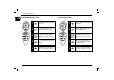
Spare parts catalogue table HB 2500 7 GB 60 46 8 44 7 47 29 30 58 31 22 50 8 23 25 39 59 18 54 53 28 33 57 45 4 14 24 26 32 9 56 17 4 13 20 16 21 19 10 27 52 2 41 40 42 49 11 43 15 55 35 48 4 37 5 3 34 38 38 37 38 37 1 12 36 36 HB2500 24 51 6
Spare parts catalogue table HB 2500 GB No. DESCRIPTION No. DESCRIPTION No.
Smaltimento delle apparecchiature obsolete Disposal of your old appliance Entsorgung von Altgeräten Élimination des appareillages obsolètes Como deshacerse de aparatos elèctricos y electrónicos fiejos Eliminação do seu antigo aparelho IT Smaltimento delle apparecchiature obsolete 1. Quando su n prodotto è riportato il simbolo di un bidone della spazzatura sbarrato da una croce significa che il prodotto è coperto dalla Direttiva Europea 2002/96/EC. 2.
ST090 R2 DOMETIC Via Virgilio, 3 - 47100 Forlì - Tel. 0543/754213 Fax.