
Operation Manual


HB2500
4
Operating instructions for users
1.1. Scope of the manual
This manual has been drawn up by the Manufacturer and is an integral
part of the machine.
The information it contains, if observed, can guarantee correct use of
the machine.
The fi rst part of the manual is for the user , while the second part is
for the expert personnel who install the machine.
To highlight some parts of the text, the following symbols have been
added:
This operation may be a source of danger.
Useful advice.
Information on being environment friendly.
1.2. Manufacturer and machine identifi cation
1.3. Machine description
This machine has been designed and built to be installed on vehicles
(motor homes, caravans, special vehicles, etc.) in order to improve
the internal temperature. When the weather is hot it supplies cool and
dehumidifi ed air; when the weather is cold it supplies hot air without
however replacing the vehicle’s original heating system. In both cases
the air temperature is adjustable.
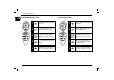
Cool air - Description of operation (FIG. 5)
The system is composed of: compressor (A), condenser (B), evaporator
(D) a 4-way switchover valve (F) and the pressurized refrigerant.
The refrigerant, by changing physical state from liquid to gas, heats or
cools the components through which it passes.
The evaporator that has been made cold is crossed by the internal air
blown by the fan (C).
It comes out cooled and dehumidifi ed. This action protracted over time
creates a reduction in the temperature inside the vehicle.
Hot air - Description of operation (FIG. 5)
The refrigerating cycle is reversed by the 4-way valve switching over
(F); the internal coil changes from evaporator to condenser, thereby
heating the air passing through it.
The system is equipped with a heating element (E) that increases the
effi ciency of the heat pump at low temperatures.
1 General information
Identifi cation
of the manufacturer
Conformity markings
Model/Serial number
Year of manufacture
Technical data
GB