INSTRUCTIONS for USE INSTALLATION INSTRUCTIONS VACUUM-TOILET for RECREATIONAL VEHICLES VT 2500 English 242 6001 - 66 T.B.
These operating instructions should be kept in a safe place. If this device is passed on, please include these operating instructions with it.
TABLE OF CONTENTS 1.0 2.0 3.0 INSTRUCTIONS INTRODUCTION FOR YOUR SAFETY 2.1 WARRNTY and CUSTOMER SERVICE 3.1 4.0 5.0 6.0 Warning and safety notices Damage in transit DESCRIPTION OF MODEL INSTRUCTIONS for USE 4 4 4 4 4 4 5 5.1 Putting into operation 5 5.2 Removing the cassette 6 5.3 Flushing the toilet 6 5.4 Cleaning 6 5.5 Putting out of operation 7 5.6 Declaration of conformity 8 INSTALLATION GUIDE Installation 10 6.1 Fixation of the rear wall of the base station 10 6.
1.0 INTRODUCTION You have made an excellent choice in selecting the Dometic Vacuum Toilet. We are sure that you will be fully satisfied with your new appliance in all respects. It meets high quality standards and guarantees the efficient utilisation of resources and energy throughout its entire life cycle, during manufacture, in use and when being disposed of. Before you start to use the appliance, please read the installation and operating instructions carefully.
.0 5.1 OPERATION Putting into operation First check whether: the cassette has been inserted correctly the vehicle water tank has been filled the power supply has been switched on (main switch). Once the power supply for the vehicle has been switched on, the toilet is also automatically switched on and a vacuum is produced in the system for the first time. The yellow LED illuminates on the display panel. After approx. 1 minute this procedure is finished. The green LED illuminates.
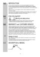
Only use commercially available toilet paper with 2 layers. Since the system always operates under a vacuum and is closed hermetically, no smell can develop. Never press the pedal whilst sitting on the toilet or if the seat lid is open! For the environment's sake, do not use any chemicals. Do not dispose any solid or non-dissolving objects such as plastic cans or paper towels in the toilet. These items can cause damage or plugging of the system ! 5.
5.4.1 Changing the filter The filter in the base station must be changed according to the number of times it has been used, at the latest, however, after three years. filter 5.5 Putting out of operation If the vehicle is not going to be used for a longer period of time, especially in the winter months, proceed according to the following instructions: 1.
5.
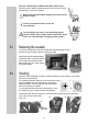
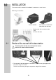
6.0 INSTALLATION The vacuum toilet is intended for installation in caravans or motor homes. Delivery includes: Toilet Vacuum cassette Base station (complete with base plate and rear wall) Display panel with connection cable 1 cap 4 screws and caps 6.1 Fixation of the rear wall of the base station The base plate and the rear wall must be assembled on the same vehicle element! back front 1.
6.2 Fixation of the floor plate of the base station 1. The floor plate of the base station is fixed to the rear wall. The floor has two lugs (A), that have to be pushed into the respective gaps in the rear wall of the base station. Make sure that the connection (B) for the carbon filter fits into the place provided! A A B C C 6.3 Fixation of the toilet Distance to the rear wall : min. 50 mm 6.4 2. The floor plate of the base station is screwed to the floor of the vehicle. 3.
6.5 Connecting pipes LED-display panel siphon siphon Fig. shows the complete VT 2500 system with pipe connection on the right-hand side (pipe connection on the left-hand side, optional) - The installation of the connecting pipes (DN 40) from the vacuum cassette to the toilet must be completely airtight and include a siphon! - The maximum length of the pipes from the toilet to the cassette is approx.
6.6 Water supply The water supply is provided with the aid of a pump (this can also be the pump available in the vehicle) and a hose connection from the fresh-water container. Fasten a hose clamp to the water-supply connection. Electrical installation 6.7 6.7.1 Electrical installation must be carried out by qualified personnel only ! . The 12V DC connection to the toilet electronics is shown in the adjacent figure. The 2-pole connection cable is connected to the electronics as shown in the figure.
6.7.2 Microswitch connection For vehicles that are not equipped with a pressurized water system, a toilet with integrated microswitch for controlling a pump must be installed. The microswitch (A) is connected in the circuit of the submergible pump so that the pump is activated via the microswitch when the pedal is pressed. A Connection cable to the pump with two wires This connection is not necessary in vehicles with a pressure controlled pump. 6.
6.9 Wiring diagram The power supply must comply with the following performance data: Vehicle battery: Voltage > 11.5 Volt Peak current (short-term) 8 Amp. Use slow-acting fuse in the feed line! These values are reached in the standard vehicle batteries. Power pack: When using a controlled fixed-voltage power pack (e.g. for application in weekend homes) one should similarly make sure that these values are adhered to. Normal rated voltage for power packs with 13.8 V at 6 A.
Dometic GmbH In der Steinwiese 16 D-57074 Siegen Tel.: +46- 8 501 025 00 Fax.: +46- 8 501 025 98 www.dometic.com Tel.: +49-(0) 271 / 692-0 Fax.: +49-(0) 271 / 692 - 300 www.dometic.