Refrigerators & Freezers ❖ INSTALLATION • OPERATION English Before installing your Tundra unit, refer to L-2083: Tundra Installation Check List.
Table of Contents Refrigerators & Freezers • Installation 3 Warnings ................................................................................................................................. 3 Locating the Data Plate 4 Inspection and Handling 4 Electrical Connection 5 DC Only Wiring ........................................................................................................................ AC/DC Wiring (AC/DC Converter) ...........................................................
Refrigerators & Freezers • Installation Warnings This section of the manual refers to essential safety Installation information for all compressor-type refrigerators and freezers (including Portable and Special Purpose Units), provided by Dometic Corporation. 1. When replacing old appliances, before disposing of the old model, any locking device with hinging must be removed so that the door cannot be accidentally locked. All refrigerant must be removed according to current EPA regulations. 2.
Locating the Data Plate The dataplate bearing the model and serial number and technical data is located on the upper right-hand section, inside the appliance (for Portable units, it is located on the inside of the lid). An additional, identical dataplate is located on the compressor’s electronic module. The first three digits of the serial number indicate the Year and Week of manufacture.
Electrical Connection Before connecting the appliance to the power supply, check that the line voltage corresponds to the indications on the appliance rating plate and those of the compressor plate. This appliance complies with EC directive 89/336 governing radio suppression. Noise emission levels are maintained below 70 dB(A). DC Only Wiring For Direct Current (DC) refrigerators, connect the appliance to the DC distribution center.
Portable Units - Special Considerations Since Portable units can be used in a variety of applications, and connected to a variety of power sources, the following must be considered: • Cigarette lighters may not provide sufficient voltage and power to start and operate a portable unit. The unit may need to be wired separately from the lighter receptacle. • Many DC outlets in vehicles (i.e. cigarette lighters, power outlets, etc.), are not powered when the ignition switch is turned to “Off”.
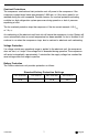
Overload Protections The compressor overload and start protection cuts off power to the compressor if the compressor speed drops below approximately 1,900 rpm, or if this motor speed is not reached during the start sequence. Possible reasons for overload protection activating could be too high refrigeration system pressures during operation or lack of pressure equalizing at start. The fan overload protection stops the compressor if the fan current exceeds 0.5 A(avg) or 1 A(peak).
ABYC Standards - ABYC Guidelines E9 - Direct Current Conductor Sizes For 3 Percent Drop in Voltage ABYC Standards - ABYC Guidelines E8 - Alternating Current/Amperage Temperature Rating of Conductor Insulation (Guidelines when using an AC/DC Converter) 60°C (140°F) 75°C (167°F) 80°C (176°F) 90°C (194°F) 105°C (221°F) 125°C (257°F) 200°C (392°F) Outside Conductor Outside Inside Outside Inside Outside Inside Outside Inside Outside Inside Outside Inside or Inside Size Engine Engine Engine Engine Engine
Final Installation Notes • For all appliances, AVOID the use of any electrical adapters or extension cords. • After installation, allow the appliance to sit for at least one hour before starting. • The manufacturer assumes no responsibility for any injuries or damage caused by noncompliance with any of the installation regulations.
Refrigerators & Freezers • Operation Warnings This section of the manual refers to essential safety Operation information for all compressor-type refrigerators and freezers (including Portable and Special Purpose Units) provided by Dometic Corporation. • Before carrying out any maintenance or cleaning operations, disconnect appliance from power supply via the circuit breaker. • • Do not put glass containers holding liquids in the freezer compartment.
Digital Thermostat (Solid State Control) (See Fig. 3, page 20) • The Digital Thermostat AUTOMATICALLY turns ON when power is applied to unit. • The thermostat displays the interior temperature constantly. To access, and/or change the Setpoint temperature, do the following: 1. Press the “set” Button to display the Setpoint temperature. The Setpoint is changed with the “up” and “down” Arrow Buttons. The last entered Setpoint will stay in memory.
Refrigerators & Freezers • Maintenance Defrosting Defrosting should be carried out whenever the frost layer exceeds a thickness of 1/8 of an inch. This is necessary to guarantee efficient refrigeration and to avoid excessive power consumption. Excess frost buildup will effect the appliance’s performance. To completely defrost, turn the appliance OFF. Keep the door/lid open to minimize the defrosting time. Do not attempt to remove the frost layer using any sharp metal instruments.
Refrigerators & Freezers • Trouble-Shooting A. Appliance Does Not Operate Check that: 1. The thermostat is not set to “STOP” or “OFF”. 2. The electrical system circuit-breaker for the appliance is “ON”. 3. The fuse between the electronic control unit and the power source has not blown. 4. The power supply cable is not faulty, loose or poorly connected. 5. The battery is delivering sufficient power. If the battery voltage is less than 10.4V (on a 12VDC system) or 22.
C. Insufficient Refrigerating Capacity Check that: 1. The door/lid is sealed properly. 2. The appliance is not positioned close to heat sources. 3. The appliance and remote refrigerating unit (if applicable) are sufficiently ventilated. 4. Excess frost has not accumulated on the evaporator. 5. Dust has not blocked the condenser. 6. The fan rotates freely (in forced air models). 7. The appliance is not over-full.
Manufacturer’s Limited Warranty Agreement The following warranty is extended to cover Tundra products supplied by Dometic Corporation and is subject to qualifications indicated. Dometic Corporation warrants for the periods set forth below that products manufactured or supplied by it will be free from defects in workmanship and material, provided such products are installed, operated, and maintained in accordance with Dometic Corporation written instructions.
Dometic Corporation – Tundra Schedule of Limited Warranty Allowances This schedule lists the maximum Dometic Corporation allowance for the repairs listed below. Items which exceed the scheduled allowances require prior approval. Sales tax, duty, mileage charges, tolls, phone calls, etc. are not covered by warranty and are the responsibility of the customer. If more than one repair is performed during the same visit, Dometic Corporation will pay 100% of the first covered repairs and 50% for all others.
WARNING Dometic Corporation, manufacturers of Cruisair, Grunert, Marine Air, Sentry and Tundra Products, makes the following safety warnings concerning the application, installation, use and care of its products. Although these warnings are extensive, there may be specific hazards which may arise out of circumstances which we have not outlined herein. Use this as a guide for developing an awareness of potential hazards of all kinds. Such an awareness will be a key factor in assuring your SAFETY and comfort.
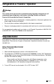
Description of Drawings/Diagrams Fig. 1 Description of an Appliance (1 - 8) 1. Mounting Flange Assembly 5. Glass shelf 2. Freezer Compartment w/ Door 6. Door Shelves/Bottle Compartments 3. Condensation Drain Pan 7. Positive Locking Door (Nautic Lock) 4. Vinyl Coated Wire Shelf(s) (Adjustable) 8. Thermostat Fig. 2 Rotary Thermostat 1. Coldest Setting 2. Adjustment Knob, Turn Clockwise Fig. 3 Digital Thermostat 1. “up” Button 2. “down” Button 3. “set” Button Fig.
Fig. 1 8. 7. 1. 2. 3. 4. 5. 6. Fig. 2 Rotary Thermostat 1. Coldest Setting 19 2. Adjustment Knob.
Fig. 3 Digital Thermostat 1. “up” Button 2. “down “ Button 3. “set” Button Fig.
Fig.
Fig.
Fig.
Fig.
Fig.
Place Data Label Here Dometic Corporation 2000 N. Andrews Ave. Ext. • Pompano Beach, FL 33069-1497 USA 954-973-2477 • Facsimile: 954-979-4414 • www.tundra.cc P.O.