
Product specifications
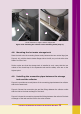
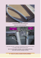

4.7 Fastening the collector on the mounting frame
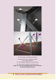
Attach first the lower collector support bar in the mounting frame, as it shown in
the upper photo of Figure 4.7a. Please do not tighten fully the screws.
Bring and put the collector on the mounting frame. Make sure that the (not fully
tighten) lower collector support bar (its upper edge) is inserted in the notch existing
in the collector frame (see Figure 4.7a, lower photo).
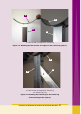
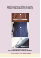
Bring and attach the upper collector support bar, as shown in Figure 4.7b. Again
make sure that the upper collector support bar (its lower edge) is inserted in the
notch of the collector frame.
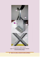
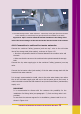
It is emphasized that it is necessary to place the collector, so that it has a slight
upward tilt to the right, as you look at it from the front (Figure 4.1a). If it is tilted
in the wrong direction, the solar water heater will not function properly (improper
thermosiphonic flow / natural convection).
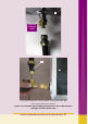
Finally, tighten all bolts and nuts of the lower and upper collector support bars.
CAUTION
Please use, in a sunny day, an opaque material (from the packaging or
other) to cover the glass of the collector. The collector must remain covered
until the completion of the installation i.e. until the storage tank is filled with
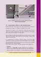
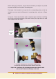
22. Vertical leg 23. Inclined (45
o
) leg 25. Horizontal connector
Figure 4.6 Attaching the horizontal connector between the inclined
and the vertical legs (Step 4).
22
24
23
25