
Product specifications
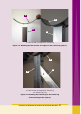
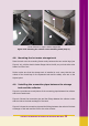
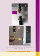

Before making any connection, the pipe thermal insulation (see Figure 4.10) should
be passed outside from the plastic connecting pipes.
The length of the insulation is longer than the corresponding pipes, so that the
insulation can cover also the fittings at all connecting points, as shown in Figure
4.11.
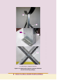
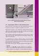
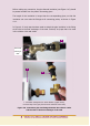
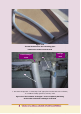
In Figure 4.12 vinyl tape has been used to attach the pipe insulation in the fitting
at the inlet to the heat exchanger of the tank. Similarly vinyl tape has to be used
in the collector inlet and outlet.
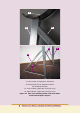
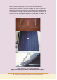
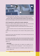
1. Hot water storage tank 2. Solar collector (upper corner)
8. Closed loop “hot” pipe (flow from the collector to the tank)
Figure 4.8. Connection pipe and fittings between the collector outlet
and the inlet to the heat exchanger of the tank
Tank heat
exchanger
inlet
8
1
8