
User Manual
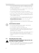
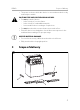
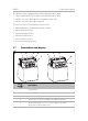
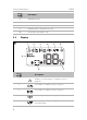
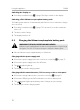
Table Of Contents
- 1 Explanation of symbols
- 2 General safety instructions
- 2.1 General safety
- 2.2 Operating the device safely
- 3 Scope of delivery
- 4 Intended use
- 5 Technical description
- 5.1 Connections and display
- 5.2 Display
- 6 Using the appliance
- 6.1 Before first use
- 6.2 Starting and switching off
- 6.3 Charging the lithium iron phosphate battery pack
- 6.4 Checking the charge level
- 6.5 Connecting consumer devices
- 6.6 Replacing fuses
- 7 Troubleshooting
- 8 Maintaining and cleaning the product
- 9 Warranty
- 10 Disposal
- 11 Technical data

Technical description PLB40
8
5.2 Display
6 Adjustable handle
7 2x fuse holder
8 AC/DC adapter input socket
9 DC/DC Anderson™ SB™ input socket
10 Reset button (beneath the cap)
No. in
fig. 3
Description
1 A failure occurred (chapter “Troubleshooting” on
page 12).
2 See chapter “Troubleshooting” on page 12.
3 See chapter “Troubleshooting” on page 12.
4 The battery pack supplies energy to an USB device.
5 The battery pack supplies energy to a device connected to
the 2-PIN output.
No. in
fig. 2
Description
!
211111 3 4 5 6
78
9
3
!
DometicPLB40_OPM_4445102605_APAC(en)_20xx-xx-xx.book Seite 8 Mittwoch, 2. Dezember 2020 9:02 09