INSTALLATION AND OPERATING INSTRUCTIONS REFRIGERATOR FOR LP-GAS AND ELECTRIC OPERATION RA/RM-1D RA/RM-2D AES III FOR YOUR SAFETY RM 2355 If you smell gas: 1. Open windows and door. 2. Don’t touch electrical switches. 3. Extinguish any open flame. 4. Immediately call your gas supplier. FOR YOUR SAFETY RM 2455 RM 2555 Do not store or use gasoline or other flammable vapors and liquids in the vicinity of this or any other appliance.
OPERATING AND INSTALLATION INSTRUCTIONS FOR RM 2355, RM 2455, RM 2555 & RM 4605 INTRODUCTION CONTENTS We are pleased that you have chosen this refrigerator and hope you will derive much satisfaction from using it. OPERATING INSTRUCTIONS _______________________ 4 The refrigerator is designed for installation in motorhomes and intended for storage of foods, frozen foods and making ice. It comes with Automatic Energy Selector (AES) which controls operation and energy supply.
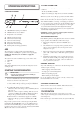
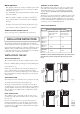
LP GAS OPERATION OPERATING INSTRUCTIONS AES will select LP gas operation under the following conditions: CONTROL PANEL D ON 1 F When the system chooses LP gas operation, the flame failure device is automatically opened, allowing the gas to flow to the burner. At the same time, the electronic igniter is energized. 3 2 OFF C A • No AC (230-240V) available • Engine not running (no high current at 12V DC available) B E C After initial installation, servicing, or changing gas cylinders etc.
SWITCHING BETWEEN ENERGY SOURCES DEFROSTING When switching from one energy source to another, there are some delays implemented in the AES system. The 15 min. delay between switching off the engine and starting gas mode is intended to delay the starting of gas mode e.g. when stopping at a filling station. Frost will gradually accumulate on the refrigerating surfaces. Each time the door is opened some of the cold air in the refrigerator spills out and is replaced by warm moist room air.
CLEANING THE REFRIGERATOR PRODUCT CARE - SOME USEFUL HINTS Clean the inside of the refrigerator regularly to keep it fresh and hygienic. Make sure that: • Defrosting is carried out periodically. • The refrigerator is clean and dry with the door left open when it is not to be used for some time. • Liquids or items with a strong odour are well packed. • The ventilation openings are unobstructed. • The doors are secured by means of the travel catch when the motorhome is on the move.
MAINTENANCE REMOVAL OF FLUE GASES The ventilation passage at the rear of the recess, between the outer wall of the vehicle and the refrigerator must be sealed off against the living space, so cold draughts are excluded (winter camping) and no flue gases can penetrate into the motorhome. • This appliance must be serviced by an authorised person. We recommend that an authorised service technician checks the refrigerator once a year.
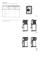
CLEARANCES Minimum clearances (mm) to combustible materials are: G 1 RM 2355 (Fig. 5 & Fig. 6) RM 2455 - RM 2555 - RM 4605 (Fig. 5 & Fig. 7) G Top 0 0 K Side 0 0 L Bottom 0 0 M1 Rear 25 0 K K L Fig. 5 The distance between the rearmost part of the refrigerator and the wall behind the refrigerator. M M Fig. 6 RM 2355 M M Fig.
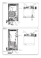
CONNECTING POINTS Dimensions to connecting points (mm).
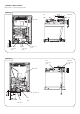
RM 2555 Gas connection point Electrical connection point Flue outlet pressure test point Electrical connection point Gas connection point RM 4605 Gas connection point Flue outlet Electrical connection point Gas pressure test point Gas connection point 10 Electrical connection point
INSTALLATION/BUILDING-IN SECURING THE REFRIGERATOR The refrigerator must not be exposed to radiated heat from hot objects. Excessive heat irradiation impairs performance and leads to increased energy consumption. For this reason the refrigerator should be installed if possible not at the entrance side of the vehicle - normally orientated south and often with an awning which would impair the dispersion of heat and combustion gases from the ventilation openings.
DRAIN WATER HOSE b) Once the lower front strip is slipped under the hinge, the part is possible to swing into place as shown in Fig. 13. A hole must be drilled through flooring see Fig. 16 / 17. The installer has to make sure that the hose does not kink when run through the floor. Seal around the hose that goes through the drilled hole. 3 Fig. 13 c) 2. Fig.
ELECTRICAL CONNECTION CROSS-SECTIONS The electrical installation must be carried out by authorised personnel. The D+ (alternator) is a signal cable and therefore 1-1.5 mm2 is sufficient. Connection to 12V + and - must be done with a 10 mm2 wire if the total wire length (+ and - wire together) is maximum 12 m. If longer leads are needed, bigger dimensions are required. NOTE! For mains voltage operation, it is important that the circuit to and in the motorhome is effectively earthed.
With screws With screws (see Fig. 20 and Fig. 22) Snap in To mount the door panel, follow these steps: RM 2455 1. Open the door 90 degrees. 2. On new refrigerators, the decoration strip is taped inside the door; if installed on the door, remove the door decoration strip (2) by removing its three screws (1). 3. Remove the old panel. 4. Insert the new panel by inserting the vertical edges into the grooves of the door frame (3).
POSITIONING OF SHELVES 2 1 ��������������������������������� ������������������������������������������� ������ 3 4 ����������������������������������������� ��������������������������������������� �������������������������������������������������� 6 5 ���������������������������������������������� �������������������������������������������� ���������� 15
TECHNICAL DATA RM 2355 RM 2455 RM 2555 RM 4605 Height (mm) 766 948 1104 1385 Width (mm) 556 632 632 632 Depth incl. cooling unit (mm) 577 627 627 627 Height (mm) 756 928 1083 1365 Width (mm) 521 602 602 602 Depth (mm) 542 610 610 610 90 121 150 186 29 39 44,5 56,5 240V 175 175 175 325 12V 175 175 175 275 1.10 1.16 1.16 1.
REARVIEW EQUIPMENT RM 2355 Heaters Flue baffle Reigniter Relay Drain water hose Power module cover (PC board) Protection cover Inlet fitting D+ Terminal block 12V DC only Flexible cord Screw for protection cover Burner jet Manual gas shutoff valve D+ 12 or 24V DC RM 2455 - RM 2555 Heaters Relay Flue baffle Reigniter Power module cover (PC board) Protection cover D+ Flexible cord Terminal block 12V DC only Screw for protection cover Inlet fitting Burner jet Manual gas shutoff valve D+ 1
WIRING DIAGRAM RM 2355 - RM 2455 - RM 2555 RM 4605 18
WORKING INSTRUCTIONS FOR THE GAS SAFETY SYSTEM WORKING DIAGRAM Thermostat Spark Gas valve Flame detector device Lock out indication TW TS TS TWI TS TWI TS TECHNICAL SPECIFICATIONS Classification codes according to EN298 A-M-R-V-X-K Class of protection according to Low Voltage Directive IP-20 Waiting time / TW 8s Safety time / TS 45 s Inter-waiting time / TWI 120 s Working temperature –20°C to +45°C Nominal working voltage* 12 - 13,8V DC Resistance to vibration according to EN60068-2-6:1995
APPENDIX A - AIRING POSITION CARD Use the Airing Position Card to keep the doors ajar if the refrigerator will not be in use for an extended period of time or put in storage.
APPENDIX A - AIRING POSITION CARD RM 4605 2 1 4 3 21 5
NOTES
MO-M 0552