INSTRUCTIONS FOR USE INSTALLATION INSTRUCTIONS ABSORPTION - REFRIGERATOR for CARAVAN and MOTORHOME RM 7271 L RM 7275 L RM 7291 L RM 7295 L RM 7361 L RM 7365 L RM 7371 L RM 7401 L RM 7405 L Record for future reference: Model number ............................................. Product number ............................................. Serial number ............................................. AUS English Type C40 / 110 822 6100 - 52 T.B.
www.dometic.com Safety instructions Instructions for storing food in a refrigerator: No refrigerator of any kind can improve the quality of the food; refrigerators can only maintain the food's quality for a short duration as from the time of storing it.
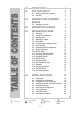
TABLE OF CONTENTS 1.0 2.0 Information 3.0 4.0 5.0 6.0 INTRODUCTION FOR YOUR SAFETY 4 4 2.1 2.2 Warning and safety notices Coolant 4 4 WARRANTY AND CUSTOMER SERVICE 5 3.1 5 Damage in transit DESCRIPTION OF MODEL REFRIGERATOR GUIDE 5 5 5.1 5.2 5.3 5.4 5.5 5.6 5.7 5.8 5.9 5.10 5.11 5.12 5.13 5.14 5.15 5.16 5.17 5.18 5.19 5.
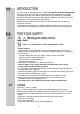
1.0 INTRODUCTION You have made an excellent choice in selecting the Dometic Absorption Refrigerator. We are sure that you will be fully satisfied with your new appliance in all respects. The appliance, which works silently, meets high quality standards and guarantees the efficient utilisation of resources and energy throughout its entire life cycle, during manufacture, in use and when being disposed of.
3.0 WARRANTY AND CUSTOMER SERVICE Warranty arrangements are in accordance with the normal conditions applicable for the country concerned. For warranty or other servicing, please contact our Dometic Service department. Any damage due to improper use is not covered by the warranty.
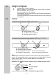
5.2 Using the refrigerator The cooling unit is silent in operation. When the appliance is first put into operation, there may be a mild odour which will disappear after a few hours. Ensure the living area is well ventilated. The refrigerator will take several hours to reach its operating temperature in the cooling compartment The freezer compartment should be cold about one hour after switching on the refrigerator. 5.2.1 Controls A. Manual energy selection MES (e.g.
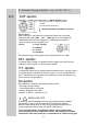
Proceed to the description that applies to YOUR model. A. Manual Energy Selection 5.2.2 Electrical operation 1. 12V - operation (DC) The refrigerator should only be used while the motor is running, otherwise the on-board-battery would be discharged within a few hours! B A C 1. Set energy selector switch (A) to 12V . Operating display “C”, 12V lights “green”. Appliance is in function. 2. Use rotary switch (B) to regulate the temperature in the main refrigerator compartment.
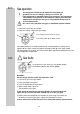
5.2.3 Gas operation The refrigerator should only be operated using liquid gas (propane). Do not use Autogas, town gas or natural gas. If the refrigerator is operated during travel using gas, the precautions stipulated by the legislation in the respective country must be taken . Operating the refrigerator with gas is not permitted during travel in France and Australia. As a basic rule, operation using gas is prohibited in petrol stations. 1. Open the valve of the gas cylinder 2.
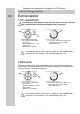
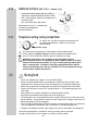
B. Automatic Energy Selection (only with RM 7XX5 L) 5.2.5 “AUTO”-operation RM7XX5 L - models are equipped with an “AUTO”-MATIC function. Set energy selection switch (A) to position “AUTO” . The LED "AUTO" illuminates. Manual operation is possible at any time. Explanations: Upon switching on, the electronics automatically select one of the three possible energy types: 230V - 12V - liquid gas.
5.2.6 Additional functions (RM 7XX5 L - models only) D Temperature setting display (D) with 4 LED to indicate the selected temperature (MIN - MAX) LED - dimmer (E) for adjusting the brightness of the display-LED (only accessible when door opens) Underneath the fascia is a knurled knob for adjusting the brightness (see item E above) 5.2.
5.4 Making ice cubes Ice cubes are best frozen overnight. At night, the refrigerator has less work to do and the unit has more reserves. 1. Fill the ice cube tray with drinking water. 2. Place the ice cube tray in the freezer compartment. Only use drinking water! 5.5 Defrosting As time goes by, frost builds up on the fins. When the layer of frost is about 3mm thick, the refrigerator should be defrosted. 1. Switch off the refrigerator, as described in Section 5.8 - "Switching off". 2.
5.7 Door locking close open park-position / vent-position 5.8 Switching off A 1. Set energy selector switch (A) to position "0" (OFF). The appliance is now fully switched off. 2. Secure the door open by means of the door stop. The door will be slightly ajar. This is to prevent mould from forming inside the appliance. Switching off gas operation If the refrigerator is to be taken out of service for an extended period of time, the on-board shut-off valve and the cylinder valve must be closed. 5.
5.10 Interior light Changing the light bulbs 1. 2. 1. Remove cover. 90° 2. Detach defective light bulb. 3. Fit new light bulb Note: For 12V DC : 1 light bulb 12V, 2W Please contact Dometic Service Centres for replacement light bulbs. 4. Clip the cover back in place. 5.11 Changing the decor panel 2. Take off the door by moving it upwards. 1. Open the door and loosen the hinge screw. 4. Remove the decor plate and insert a new decor plate. 5. Screw the door strip back in position. 3.
5.12 Changing the doorhang It is not always possible to change the door when the refrigerator is installed. 1. Open the door, unscrew the hinge screw and keep it to hand. 2. Take off the door by moving it upwards. 6. 7. 3. 4. 8. Screw the hinge screw back in. 5. Attach the door.
5.13 Troubleshooting Before calling the authorised Service Department, please check whether: 1. The instructions in the section "Using the refrigerator" have been followed. 2. The refrigerator is not tilted excessiveley. 3. It is possible to operate the refrigerator with an available power source. Failure : The refrigerator does not work in gas operation mode. Possible cause Action you can take a.) Gas bottle empty. a.) Change gas bottle. b.) Is the supply cut-out device open? b.
5.14 Maintenance Works on gas components and electical installation may only be carried out by authorised personnel. We recommend to contact your Dometic Service Centre. The appliance´s gas equipment and it’s associated fume system must be inspected after installation. Afterwards an authorised technician must inspect every two years. It is the user’s responsibily to arrange for inspections after purchase.
5.19 Technical data Model Dimensions H x W x D (mm) depth incl. door RM 7271(L) RM 7275(L) RM 7291(L) RM 7295(L) RM 7361(L) RM 7365(L) RM 7371(L) RM 7401(L) RM 7405(L) 821x486x541 821x486x541 821x525x541 821x525x541 821x486x541 821x486x541 821x486x606 821x525x541 821x525x541 Gross capacity Usable Connection incl. freezer capacity of Mains / Battery compartment freezer compartment 77 lit. 77 lit. 86 lit. 86 lit. 88 lit. 88 lit. 89 lit. 97 lit. 97 lit. 9.5 lit. 9.5 lit. 10.5 lit. 10.5 lit. 9.5 lit. 9.
6.0 INSTALLATION GUIDE On installation of the appliance, the technical and administrative regulations of the country in which the vehicle will first be used must be adhered to. Otherwise the refrigerator must be installed as described in these instructions. In some OEM applications it may not be possible for these instructions to be followed exactly. In this case an authorised Dometic representative may issue supplementary instruction. 6.
6.2 Draught-free installation The refrigerator shall be sealed so that fumes cannot enter the living area. Illustrated below are two typical approved methods of sealing. Do NOT use any easily inflammable materials (in particular silicone sealing agent or similar) for sealing! The device manufacturer's product liability and guarantee shall lapse if such materials are used. Proposal 1: FIG. 1 Using the Installation Sealing Kit from Dometic (SP.No.
In this case, for gas operation, do not use the upper winter covering! If even with draught-free installation a fume chimney is desirable, you must incorporte the L100 ventilation and extraction system into the upper air vent opening. Installation of fume chimney: please refer to point “6.7”. Deviations shall require the consent of the manufacturer. 6.
6.4 Installing the ventilation system L 200 L 100 To install the ventilation grilles, cut two rectangles (451mm x 156mm) in the outer wall of the vehicle (for position of the cuts, see point “6.3”). Item 1 does not apply for installation framess with an integrated seal. 1. Seal the mounting frame, making it waterproof. 2. Insert the frame ... ... and screw into position. 3. Insert the ventilation grilles. 4. Lock the ventilation grilles. 5.
6.5 Installation recess The refrigerator must be installed draught-free in a recess (see point “6.2”). The measurements of the recess are given in the table below. Step (A) is only required for cabinets with a step. Push the appliance far enough into the recess until the front edge of the refrigerator casing is flush with the front of the recess. Allow a gap of 15-20 mm between the back wall of the recess and the refrigeration unit.
6.7 Fume extraction Fume extraction must be arranged in such a way as to provide complete extraction of all products of combustion to an area outside the living area. The flue system must slope in an upward direction in order to avoid a build-up of condensation. An installation that is not carried out by qualified persons causes a reduction in the cooling capacity and will jeopardize the manufacturer's guarantee. 6.7.1 Fitting the fume flue in the upper ventilation grille min. 10 mm max. 20 mm 1.
6.8 Gas installation The rules in point 6.1 must be adhered to. When running on gas, these appliances are intended exclusively to use liquid gas (propane) - under no circumstances should town gas or natural gas be used. An AGA Approved LP Regulator must be fitted to the gas supply. The pressure regulator must concur with the operating pressure specified on the data plate of the appliance. The operating pressure corresponds to the standard pressure of the country of specification.
6.9 Electrical installation Electrical installation may only be carried out by qualified personnel. The connection cables must be laid in such a way that they do not come in contact with hot components of the unit/burner or with sharp edges. The electrical installation must comply with national regulations. It is advisable to run the incoming supply through an on-board fuse or automatic circuit breaker.
6.9.3 D+ connection and Solar Control connection ( AES only ) D+ connection The D+ control connection must be connected to the respective vehicle terminal (alternator signal while motor is running). Solar control input (S+): Connection only when using a solar system with a solar charging controller with AES output. The respective solar charging controllers are available from a specialized dealer.
6.9.6 Wiring diagram Wiring diagram for RM 7XX1 L - models and RM 7XX5 L - models ignition unit Connections: ionisation plug A = Ground heating element DC B = Plus heating element DC C = Ground electronics D = Plus electronics ignition plug Reed contacts (sensor switching) Ground gas burner heating element DC lighting DC valve permanently connection DC C temp.
Dometic GmbH In der Steinwiese 16 D-57074 Siegen GERMANY www.dometic.