Service-Instruction COOL 3110 ABSORPTION REFRIGERATOR + OVEN for RECREATION VEHICLES RMT 7650 RMT 7850 RMT 7651 RMT 7851 RMT 7655 RMT 7855 Publications-Nr.: 599 5230-23 DE © Dometic GmbH - 2005 - Subject to change without notice T.B.
Table of Contents Page 1.0 Description of Model . . . . . . . . . . . . . . . . . . . . . . . . . . . 3 2.0 Operating . . . . . . . . . . . . . . . . . . . . . . . . . . . . . . . . . . . . 5 3.0 Components . . . . . . . . . . . . . . . . . . . . . . . . . . . . . . . . . . 6 4.0 Installation . . . . . . . . . . . . . . . . . . . . . . . . . . . . . . . . . . . 10 5.0 Optionen . . . . . . . . . . . . . . . . . . . . . . . . . . . . . . . . . . . . . 16 6.0 Service/Maintenance/Tables . . . . .
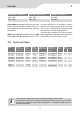
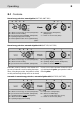
Models 1 PIEZO RMT 7XX0 Series MES RMT 7XX1 Series AES RMT 7XX5 Series RMT 7650 RMT 7651 RMT 7655 RMT 7850 RMT 7851 RMT 7855 Piezo-fridges are equipped with a manual energy selector and a thermostatic regulation of the cooling compartment temperature during 230V and gas operation. ped with electronics for controlling the function elements and status indication of the active operation source. Additionally AES-fridges provide the possibility of manual energy selection.
1 Models 1.2 General Remarks Main components accessible via ventilation grille and control panel. If no supply voltage is available the LED lights "red" at AES appliances. It does not light at MES appliances. At AES models the selected energy is displayed by the corresponding LED (i.e. 230V) and the "AUTO" LED simultaneously. Fridge does not necessarily have to be deinstalled for service and alteration. Gas supply point on back of fridge; accessible via lower ventilation grille.
Operating 2 2.
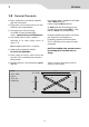
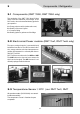
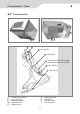
3 Components / Refrigerator 3.1 Components (RMT 7650, RMT 7850 only) The equipping of the RMT 7XX0 (piezo)-fridges differs from the traditional piezo-fridges of the RM7-series, due to the standard battery-igniter for gas operation. A = Energy selector switch (underneath cover) B = Battery of the oven’s igniter C = Compact fitting D = Battery igniter for gasburner of the fridge A C B D 3.
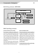
Components / Refrigerator 3 3.4 Wiring scheme (MES/AES) D+ Solar POWER MODULE BURNER CONTROL DEVICE 12 V- DC-heating element 230 V~ 12 V- AC-heating element Temp. Sensor Interior light 12 V/2 W GAS VALVE Ignition electrode Ionisation electrode 3.5 Operating priniciple Function electronics (Power module) Burner Control Device P810 The electronics regulates the controlling of the function elements according to the selected energy source, e.g. power supply of the Burner Control Device.
3 Components / Refrigerator 3.6 Gas operation components At the backside of the fridge the gas (safety) valve and the burner control device is assembled, which are operated with approx. 1.5V, controlled by the electronics.
Components / Oven 3 3.
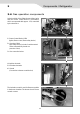
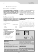
4 Installation 4.1 Electrical installation Power line connection It is advisable to run the incoming supply through an 2 Amps on-board fuse or automatic circuit breaker. The power cable must be laid in such a way that it does not come in contact with hot components of the cooling unit/burner or with sharp edges. The power must be supplied via a properly earthed socket outlet or hardwired connection. Where a socket outlet is used for the mains connection lead, the outlet must be freely accessible.
Installation 4 Terminal block MES RMT 7xx1 above red: + cable 12 V heatingelement via ignition operated relay and fuse 20A white: – cable 12 V heatingelement violett: + cable 12 V permanent connection to electronics black: – cable 12 V permanent connection to electronics D+ = Input Dynamo+ from alternator S+ = Input control signal from solar charge regulator red black white violet Fig.
4 Installation 4.2 Wiring diagram heating element DC 1.
Installation 4 2. Wiring diagram RMT 7651, RMT 7851 permanently connection DC C D Burner Control Device ionisation electrode ignition unit ignition plug Ground gas burner terminal block heating element DC Switch Frame Heating B Gas Valve A Reed contacts (sensor switching) heating element DC temp.
4 Installation 3. Wiring diagram RMT 7655, RMT 7855 permanently connection DC C Burner Control Device D ionisation electrode ignition plug ignition unit Ground gas burner terminal block heating element DC Switch Frame Heating Gas Valve B A Reed contacts (sensor switching) temp.
Installation 4 4.3 Gas-Connection The gas connection to the appliance is effected by means of a suitable coupling tube fitting L8, DIN 2353-ST, complying with EN 1949 (e. g. Ermeto). ! DO NOT UNSCREW THE PRE-INSTALLED GAS CONNECTIONS ON THE VALVE WHILE INSTALLING THE FRIDGE ! 1 Gas valve GV100 2 Gas connection 1 2 SW 14 max. 15 Nm SW 17 Observe torques in the case of exchange the gas valve. max.
5 Options 5.1 Upgrading MES – AES can fast and easily be carried out by an authorised service partner or a dealer. Purchasing an appliance RMT 7xx1 for manual operation, the customer has also the possibility to upgrade the appliance to the RMT 7xx5 with automatic energy selection. The possibility of free manual energy selection remains. An MES-fridge can be upgraded without taking it out of the recess.
Options 5 12V operation is only "active" while engine is running (D+ signal from alternator). Upgrade kit The kit includes : AES-Power-Module Sitck-on lable D+/S+-Upgrade-cable Quick clamping connector New panel Alteration of RMT 7XX1 into model RMT 7XX5 D+/S+ upgrade cable included in the supply Pull off control knobs and put aside. Loosen both screws and remove panel.
6 Service/Maintenance/Tables 6.1 Gas valve GV100 Situation B : no D+ signal cable installed in vehicle Insert black strand of "D+/S+" cable up to the stopper into the quick clamping connector together with the red cable A (+ terminal heating element, terminal 6) and press connector together. ground Pin 2 Pin 1 12V operation is "active" in ignition lock position "1" (i.e. engine not running!) 6.
Service/Maintenance/Tables 6 6.4 Electronics / Power module NTC - Table of resistance Temperature in °C 0 5 10 15 20 resitance in kOhm 27,70 22,29 18,07 14,74 12,11 6.5 12 V DC/Current draw MES RMT 7XX1 AES RMT 7XX5 AC mode Gas mode Auto AC mode Auto Gas mode ca. 50 – 60 mA ca. 60 – 70 mA • • ca. 60 – 80 mA* ca. 70 – 90 mA* ca. 70 – 90 mA* ca.
6 Service/Maintenance/Tables 6.
Service/Maintenance/Tables 6 6.
7 Further Documentation 7.1 Service Bulletin 1. Dismantle the fascia (grid) above the fridge, installed by the OEM. The chimney is accessible. 2. Release the chimney tube and push it up. 3. Disconnect the 12V- and the gas connection. The connections are on the backside of the oven. When the fridge is built in correctly, the connections are accessible after taking out the upper vent grill. 4. Take off all turning knobs cautiously.
Notes 23
Dometic GmbH Technisches Büro Service Dokumentation In der Steinwiese 16 D-57074 Siegen Tel.: +49 (0) 271 / 692-0 Fax.: +49 (0) 271 / 692-322 www.dometic.de/caravan www.dometic.