Installation instructions Absorption Refrigerator for Recreation Vehicles RM 8400 RM 8401 RM 8405 RM 8500 RM 8501 RM 8505 RM 8550 RM 8551 RM 8555 RMS 8400 RMS 8401 RMS 8405 RMS 8460 RMS 8461 RMS 8465 RMS 8500 RMS 8501 RMS 8505 RMS 8550 RMS 8551 RMS 8555 RML 8550 RML 8551 RML 8555 RMSL 8500 RMSL 8501 RMSL 8505 MBA 06/2010 Type C40 / 110 822 6102 - 00 N 5-1 English
Dometic GmbH In der Steinwiese 16 D-57074 Siegen www.dometic.
Table of contents 1.0 General . . . . . . . . . . . . . . . . . . . . . . . . . . . . . . . . . . . . . . . . . . . . . . 4 1.1 1.2 1.3 1.4 1.5 1.6 1.7 Introduction . . . . . . . . . . . . . . . . . . . . . . . . . . . . . . . . . . . . . . . . . . . . . . . . . . . . . . . . . . . . . . . . Guide to these operating instructions . . . . . . . . . . . . . . . . . . . . . . . . . . . . . . . . . . . . . . . . . . . . Copyright protection . . . . . . . . . . . . . . . . . . . . . . . . . . . . . . . . . .
General 1.0 General 1.1 Introduction No part of these instructions may be reproduced, copied or utilised in any other way without written authorisation by Dometic GmbH, Siegen. On installation of the appliance, the technical and administrative regulations of the country in which the vehicle will first be used must be adhered to. Otherwise the refrigerator must be installed as described in these instructions.
General CAUTION! 1.6 All information and guidance in these operating instructions were prepared after taking into consideration the applicable standards and regulations as well as the current state of the art. Dometic reserves the right to make changes at any time which are deemed to be in the interest of improving the product and safety.
Safety instructions 2.0 Safety instructions 2.1 Application according to regulations WARNING! Never open the absorber cooling unit! It is under high pressure. This refrigerator is designed for installation in recreation vehicles such as caravans or motorhomes. The appliance has been typeapproval tested for this application in accordance with the EC Gas Directive. There is a danger of injury! The refrigerator is to be used solely for storing foodstuffs. 2.2 2.
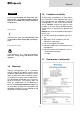
Description of model 3.0 Description of model 3.1 3.2 Model identification Refrigerator rating plate Example : The rating plate is to be found on the inside of the refrigerator. It contains all important details of the refrigerator. You can read off from this the model identification, the product number and the serial number. You will need these details whenever you contact the customer service centre or when ordering spare parts.
Description of model 3.3 Technical data RMS 8xxx RML 8xxx RM 8xxx H T B Fig. 2 Model Fig. 3 Dimensions Gross capacity H x W x D (mm) with without Depth incl. door freezer compartment Rating details mains/battery Consumption * electricity/gas over 24hrs Fig. 4 Net weight Ignition Piezo Automat RMS 8400 821x486x568 80 / 8 lit. 85 lit. 125 W / 120 W ca.2,5 KWh / 270 g 25 kg RMS 8401 821x486x568 80 / 8 lit. 85 lit. 125 W / 120 W ca.
Installation 4.0 Installation instructions 4.1 4.1.1 Side installation Installation If the appliance is installed on the same side of the vehicle as the entrance door, it is desirable that the door does not cover the refrigerator's vents. (Fig. 5, Clearance door/ventilation grille at least 25 mm). Otherwise ventilation could be impaired which causes a loss in cooling performance. Awnings are often placed at the door side of a caravan.
Installation 4.1.2 Side installation with floor-roof ventilation Proper ventilation of the refrigerator can also be achieved by lower air intake aperture in the floor and upper roof exhaust vent (see Fig. 7). A flue has to be provided between the top edge of the refrigerator and the roof ventilation which directs the hot air and the exhausts straight to the air vent in the roof. The floor opening must have a cross section of at least 250 cm² . Protect the opening, e.g.
Installation WARNING! By no means use durable sealing compounds, fitting foam or similar material to realise draught-proof installation of the refrigerator! Do NOT use any easily inflammable materials for sealing (in particular silicon sealing compound or similar). Risk of fire! The device manufacturer's product liability and warranty shall lapse if such materials are used. Fig. 10 Proposal 1 The lip seals (1) are installed at the bottom and on each side in the installation recess (Fig. 1113).
Installation The refrigerator is later pushed into the installation recess from the front. Ensure that the seals abut the case evenly. This installation option facilitates the removal and installation of the appliance for servicing. Flue duct Fig. 16 Proposal 2 Deviations require the consent of the manufacturer! Fasten the sealing lips to a stop bar on the rear side (1), e.g. by gluing. 1 4.
Installation 4.3 Installing the ventilation system The LS 100 upper vent system kit consists of the mounting frame (RS 1640), the air grille including flue gas duct (AS 1620) and the winter cover (WA120). The LS 200 lower vent system kit consists of the mounting frame (RS 1650), the air grille (AS1 630, but without flue gas duct) and the winter cover (WA130). LS 100 Fig. 17 1 Fig. 19 1 LS 200 2 ventilation aperture 2 (d = 20 - 40 mm) ventilation aperture Fig.
Installation To install the ventilation grilles, cut two rectangles (451 mm x 156 mm) in the outer wall of the vehicle (for position of the cuts, see point 4.2). 4.4 Exhaust gas duct and installing the fume flue The exhaust gas duct system must be made in such a manner as to achieve a complete extraction of combustion products to the outside of living space. The duct system must slope in an upward direction in order to avoid a build-up of condensate. The type of exhaust gas duct shown in Fig.
Installation 4.5.1 Installation in the recess Note: When installing the appliance ensure that the door hinges are supported. Figure 28 shows the optimum installation of the refrigerator, whereas Fig. 29 shows the minimum requirement with the maximum clearance between installation area and end of hinge. If the installation is carried out as per Fig. 30, the hinge is not capable of supporting the possible load in the door.
Installation 4.5.2 Recess dimensions Fig.
Installation 4.6 Securing the refrigerator 4.7 In the sidewalls of the refrigerator, there are four plastic sleeves for securing the refrigerator. The sidewalls or strips attached for securing the refrigerator must be prepared to hold the screws firmly in place even when under increased load (while the vehicle is moving). Fastening screws and caps are supplied with the refrigerator.
Installation Model RML 8xxx Model RML 8xxx, frameless decor panel 1 2. 3. 4. Fig. 38 2 2 1 1. Fig. 35 CAUTION! Fig. 39 3 Fig. 37 Fig. 36 Fig. 40 Decor panel dimensions : 4 Casing width 525 mm Height Width Thickness 1169,5 +0/-1 mm 507,5 +0/-1 mm max. 1.7 mm Fig.
Installation 4.8 Gas installation The refrigerator must be equipped with a shut-off valve allowing to cut the supply line. Such a shut-off device must be readily accessible to the user. WARNING! The gas connection shall be carried out by specialised personnel* only. * Specialised personnel are accredited experts who are able, by virtue of their training and knowledge, to vouch for the correct installation and implementation of the leakage test. Observe the regulations stated in section 2.
Installation 4.9 Electrical installation 4.9.2 Battery connection The machine's 12V connection cable is connected (observing correct polarity) to a terminal strip. The wiring for the heating element (refer to A, B wiring diagram connections; connection cable white/red) must be direct and by the shortest possible route to the battery or electric generator. WARNING! The electrical installation shall be carried out by qualified personnel only.
Installation 4.9.3 Terminal block on the appliance Connections : A = Ground heating element DC B = Positive connection, heating element DC C = Ground electronics D = Positive connection, electronics D+ S+ D+ = Alternator signal S+ = AES input signal from solar charge regulator on the vehicle Fig. 45 S+ - connection: on the appliance - + C D D+ S+ - + A B on the vehicle Fig.
Installation 4.9.5 Wiring diagrams Wiring diagram RM8xx0 : Fig.
Installation Wiring diagram RM8xx1 : Fig. 47 For MES and AES it is compulsory to provide a permanent 12V DC supply at the terminals C/D (permanent voltage supply for functional electronics).
Installation Wiring diagram RM8xx5 : Fig. 48 For MES and AES it is compulsory to provide a permanent 12V DC supply at the terminals C/D (permanent voltage supply for functional electronics).
Installation 25
www.dometic.