B)TDometic SERVICE United States SERVICE OFFICE DOMETIC SALES CORP 509 South Poplar LaGrange, IN 46761 SERVICE MANUAL Edition 2 REFRIGERATOR RM182B When ordering spare parts always state: MODEL.
TABLE OF CONTENTS A. B. c. D. E. F. G. H.
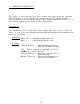
A. INSTALLAT ION INSTRUCT IONS The design of this refrigerator has been certified and approved by the American Gas Association and the Canadian GAS Association for Recreational Vehicles. This certification is dependent, however upon proper installation’-and the use of the venting components as shown in these instructions.
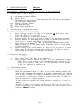
B. INSTRUCTIONS FOR USE RM182B The Controls : Controls are located at the top of the refrigerator. 1. Control Panel : Fig. 1 Page 1 ___ “A” - Air Pump and Piezo Lighter "B" - Safety Valve "C" _ Thermostat for Gas and 120 Volt Operation (12 volt has no thermostat, the unit runs continously) Voltage Selector Switch Gas Shut-Off Valve Flame Pilot Sight Peep 2. Gas Operation - Lighting the Burner _________ ____________ ____ ___________ 1. 2. 3. 4. 5. 6. 7. 3. Place Voltage Switch "D" (Fig.
General Instructions Sealed Combustion Unit The sealed canbustion unit is made up of the burner, a fresh air intake and exhaust pipes, and a vent/air-intake assembly in the wall. The burner unit is completely sealed off’ from the interior of the van by means of the two special inlet and outlet pipes. In the vent /air-intake assembly, fresh air is drawn in one pipe and combusted gases are safely vented to the outside through the other pipe.
C. REMOVAL AND INSTALLATION OF REFRIGERATOR Remova 1 1. Disconnect electrical supply. And make sure the gas supply is shut off at its source. 2. Remove the vent /air-intake assembly on the van wall outside . a. Unscrew three self-tapping screws (A,Fig.2) then remove windscreen and separating plate b. Unscrew four screws (D,Fig.2) of the fixing fixing plate and gasket (F, Fig. 2) from the the vent casing (H,Fig. 2). of the windscreen (B,Fig.2) (C, Fig. 2). plate (E,Fig. 2) and remove caravan wall (G, Fig.
D. COMPONENT REPLACEMENT RM182B NOTE: For the removal of gas and electrical components and of the refrigerator cooling unit, the refrigerator must be removed from the kitchen cabinet (see chapter C) . 1. Replacing the electric heater _____ 1. Squeeze the heater insulation in direction of arrow (A,Fig. 8) until it clicks open. Pull open the insulation in direction of arrow ( B,Fig. 8) and remove it . 2. Unscrew fixing screw (C, Fig.
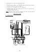
4. Pull off thermostat knob (C, Fig.11) and knob (D, Fig.11) of safety device (E, Fig. 11). 5. Unscrew union nut (F, Fig.11) of gas-pipe (G, Fig.11) from flame failure safety device (E, Fig. 11). 6. Remove three cable plug-connections from thermostat (H, Fig.11). 7. Unscrew thermo-coupling (I, Fig.11) from thermo-current adapter (J, Fig.11). 8. Unscrew thermostat (H, Fig.11) from support bracket (K, Fig.11) ( 2 screws ). 9. Unscrew two clips (L, Fig.11) from capillary tube (M, Fig.11). 10.
8. Replacing the burner-jet 12) ___ ( E Fig. ____ 1. Unscrew union nut (F, Fig. 12) of gas pipe by using a lo mm fork-spanner and a second one (14 mm) to hold counterpart the jet. 2. Unscrew burner jet from the bottom part of gas-burner. 3. Screw in the new burner jet, refit gas pipe. IMPORTANT: The gasket (G, Fig.12) between the lower part of the burner and the burner-jet must be replaced by a new one and carefully positioned to ensure that the burner is properly sealed. 9.
lo. Removing the air pump the piston. ___________ __ and replacing _____ _____ 1. Unscrew knob (A, Fig.9) of air pump (K, Fig.9) from the shaft (L, Fig.9). 2. Unscrew air pump ( 4 screws / M, Fig. 9). 3. Unscrew cover of air-pump ( 2 screws / N, Fig. 9). 4. Withdraw shaft, force out retaining disc from the groove, pull off large disc and change joint ring. 5. Reassemble in the reverse order.
F. TROUBLESHOOTING THE REFRIGERATOR - L.P. GAS CAUSE SYMPTOM NOTE: It will be noted in this guide that several causes can be responsible for one effect. The real cause or causes should be determined by the process of elimination, investigating each possible cause, starting at the top of the guide and proceeding to the bottom.
G. TROUBLESHOOTING THE REFRIGERATOR - ELECTRIC CAUSE SYMPTOM NOTE: It will be noted in this guide that several causes can be responsible for one effect. The real cause or causes should be determined by the process of elimination, investigating each possible cause, starting at the top of the guide and proceeding to the bottom.
A 8 c 13 E Fig. 2 Fig. 1 /- /-- 0 0 C \I I @I A' Fig. 4 Fig. 3 Fig. 6 Fig.
Fig. 7 I I I I I I I I I ,I I .I I I I .I ,I , I it-- II II II II II .I ‘I I I il 11 II II II II IllI I ’ II II II II I! ll II II II II II 11._ A; I -1 I I ‘I I I .I I .I .I I .I *I I I I 1 I I Fig.
E hn t-+ . c D - 1 f a I* 1 R A B f-l ,, L1--r’ 1, 1 1 I.1 L-J R I n Fig.
- C D I f-l 1, I . % i Fig.
,,-,--I_ t:i __) L --. F /E /- Q Fig.
Fig.14 .. I’ ’ II rl -- t Fig.