INSTALLATION AND OPERATING INSTRUCTIONS REFRIGERATOR FOR LP-GAS AND ELECTRIC OPERATION RA/RM-1D FOR YOUR SAFETY If you smell gas: 1. Open windows and door. 2. Don’t touch electrical switches. 3. Extinguish any open flame. 4. Immediately call your gas supplier. RM2453 RM2553 FOR YOUR SAFETY Do not store or use gasoline or other flammable vapors and liquids in the vicinity of this or any other appliance.
contents Introduction We are pleased that you have chosen this refrigerator and hope you will derive much satisfaction from using it. The refrigerator is designed for storage of foods and storage of frozen foods and making ice. The installation and servicing should only be carried out by an authorized/qualified person and conform to all relevant local authorities. It is important to read through these instructions carefully before using the refrigerator.
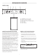
refrigerator overview Control panel A E D C B OFF AC OFF ON FUEL SELECTOR FLAME PUSH WHEN LIGHTING THERMOSTAT A. B. C. D. E. ON/OFF, Fuel selector switch Thermostat knob, Gas/Electric Flame failure safety valve push-button Piezo igniter Flame indicator General advice and information Absorption refrigerator system In an absorption refrigerator system, ammonia is liquefied in the finned condenser coil at the top rear of the refrigerator.
Installation instructions The installation, servicing and gas installation must be performed by an authorised/qualified person. The refrigerator must be installed in accordance with the manufacturers installation instructions, local gas fitting regulations, municipal building codes, electrical wiring regulations, AS5601 “Gas Installations” and any other statutory regulations.
Installation instructions Packaging Installing the refrigerator The packaging of this appliance is design to withstand the transportation from the factory to the point where it will be installed in the recreational vehicle. Before starting to install the appliance, please, make sure all parts of the packaging have been removed, so there will not be anything left that may come into contact with heat parts of the appliance or obstruct the combustion exhaust gases or the air movement around the cooling unit.
Installation instructions 2. Two screws installed in the top frame. Securing the refrigerator - Remove the top decoration panel. - Open the door. - Gently push the tabs out of the hole in the hinge with 2 a flat blade screwdriver (both sides). - Carefully tilt the top decoration panel and lift 1 to remove from the top frame. - Install the two screws in the top frame (the holes are accessible from underneath). - Seal the opening for the screws with aluminium tape. - Replace the top decoration panel.
Installation instructions 7. No bubbles should appear at the opening of the burner jet. The presence of bubbles indicates a defective gas safety shutoff, and service is required. If no bubbles were present at the burner jet, the gas safety valve is working properly. Connections LP gas connection The gas installation and servicing must be carried out by an authorised person and conform to all relevant local authorities.
Installation instructions CHANGING DOOR SWING 12 V DC connection The connection is made to the terminal block marked “12 volts DC heater”, located at the bottom left corner on the back of the refrigerator cabinet. The refrigerator must be connected to the battery circuit with two wires of adequate capacity to avoid voltage drop. The wire gauge should be chosen with consideration to the wire length in accordance with the table below. The refrigerator is equipped with a reversible door.
Installation instructions To mount the door panel - snap in Refrigerator Removal 1 1. Open the door 90 degrees. 1. Disconnect the 230- 240 V AC voltage and 12 V DC voltage leads. 2. Shut off the gas supply at the LP tank. 3. Disconnect the gas supply line. Always use a back up wrench when loosening and tightening connections. 4. Cap the gas supply line, loosen the screws anchoring the refrigerator to the enclosure and slide the refrigerator out of the compartment. 5.
operating instructions GAS and AC operation REGULATING THE TEMPERATURE The refrigerator is equipped with a thermostat that can be adjusted by turning the knob B to different setting to maintain the desired cabinet temperature. Gas operation • At “OFF, the thermostat closes its main valve and the burner runs continuously at the bypass rate, just enough to keep the burner lit. • At “MAX”, the thermostat allows the burner to remain on high flame continuously.
operating instructions Storage compartments Product care Defrosting ! WARNING 1. Shut off the refrigerator by turning the knob A to “OFF”. Do not store explosive substances in the refrigerator, such as cigarette lighter gas, gasoline, ether or the like. 2. Empty the refrigerator, leaving the drip tray under the finned evaporator. 3. Leave the cabinet and freezer doors open. Filling the ice tray with hot water and placing it on the freezer shelf can reduce defrosting time.
Maintenance & service Service and maintenance must be done on a regular schedule to keep the refrigerator operating properly, efficiently and safely. The service should only be performed by a qualified technician who is familiar with LP gas systems and refrigerators. Replacing the heater Cleaning the flue and burner Inspect the flue baffle. It should be reasonably clean and free of soot. Heavy soot formation indicates improper functioning of the burner.
Maintenance & service 13. Reinstall burner, being careful that the end of the burner fits into the slot on the burner bracket. Check to make sure slots are centered under the flue tube and the thermocouple is positioned properly (tip of thermocouple extends over two slots of burner). 14. Be sure to reconnect the wire to high voltage electrode. Check the electrode for proper location and gap. Troubleshooting Refrigerator does not cool properly • Burner jet clogged. • Check level of refrigerator.
Appendix A - Rearview equipment Heaters Cover, Terminal block Flue baffle 12 Volts DC Heater Protection cover 12 Volts DC Reigniter Evaporation Tray 12 volt terminal block Inlet fitting Flexible cord Screw for protection cover Burner jet Manual gas shutoff valve Drain water hose 14
Appendix B - wiring diagram 15