® RM2351 RM2354 RM2451 RM2454 RM2551 RM2554 RM2652 RM2662 RM2663 RM2852 RM2862 RM3862 NDR1062 FOR YOUR SAFETY If you smell gas: 1. Open windows. 2. Don’t touch electrical switches. 3. Extinguish any open flame. 4. Immediately call your gas supplier. FOR YOUR SAFETY Do not store or use gasoline or other flammable vapors and liquids in the vicinity of this or any other appliance. INSTALLATION MANUAL REFRIGERATOR FOR LP-GAS & ELECTRIC OPERATION POUR VOTRE SÉCURITÉ Si vous sentez une odeur de gaz: 1.
INTRODUCTION This manual describes the installation procedure of the following refrigerator models: RM2351, RM2354, RM2451, RM2454, RM2551, RM2554, RM2652, RM2662, RM2663, RM2852, RM2862, RM3862 and NDR1062. For information about maintenance and operating instructions, refer to the USER MANUAL (825 12 57-00). The unit must be installed by qualified personnel only. This manual should be read and understood before installation.
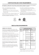
CERTIFICATION AND CODE REQUIREMENTS This appliance is certified under the latest edition of ANSI Z21.19•CSA 1.4 Refrigerators using gas fuel. The installation must conform with local codes, or in absence of local codes, the following standards as applicable. In the U.S. the installation must conform with: • National Fuel Gas Code, ANSI Z223.1/NFPA 54 (latest edition). • Recreational Vehicles Code, ANSI A119.2 (latest edition). • Manufactured Home Construction and Safety Standard, Title 24 CFR, Part 3280.
VENTILATION REQUIREMENTS VENTILATION HEIGHTS It is essential that all maximum or minimum dimensions are strictly maintained, as the performance of the refrigerator is dependent on adequate flow of air over the rear of the refrigerator.
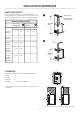
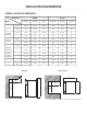
VENTILATION REQUIREMENTS OVERALL AND RECESS DIMENSIONS Dimensions Model Overall Recess Height A Width B Depth C Height H Width W Depth D RM2351 RM2354 inches 30-5/32 21-7/8 22-22/32 29-3/4 20-1/2 21-3/8 mm 766 556 577 756 521 542 RM2451 RM2454 inches 37-3/8 24-7/8 24-11/16 39-9/16 23-11/16 24 mm 948 632 627 928 602 610 RM2551 RM2554 inches 43-1/2 24-7/8 24-11/16 42-5/8 23-11/16 24 mm 1104 632 627 1083 602 610 RM2652 RM2662 RM2663 inches 54-21/32 24-7/
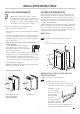
INSTALLATION INSTRUCTIONS INSTALLING THE REFRIGERATOR SECURING THE REFRIGERATOR Be careful when installing the refrigerator model NDR1062. It is equipped with the latest vacuum insulated panel technology. These insulating panels are located on the top, back, bottom, sides and doors. If the surface is punctured, loss of insulation will occur, resulting in poor refrigerator performance. For a proper installation, follow these instructions: • Make sure the floor is solid and level.
INSTALLATION INSTRUCTIONS b) Secure the refrigerator and the lower front strip with two screws: One screw through the hinge and on the opposite side and then, one screw through the lower front strip. DRAIN WATER HOSE A hole must be drilled through flooring and the installer needs to make sure the hose does not kink when run through the floor. Seal around the hose that goes through the drilled hole.
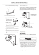
INSTALLATION INSTRUCTIONS Testing LP gas safety shut off Electrical connection The gas safety shut off must be tested after the refrigerator is connected to LP gas supply. 120 V AC connection RM2354-2454-2554-2662-2663-2862-3862 &NDR1062 To test the gas safety shut off, follow these steps: 1. Start the refrigerator. Switch to GAS mode. 2. Check that the gas flame is lit and the GAS mode indicator lamp is on. 3. Close the manual gas shutoff valve at the back of the refrigerator. 4. Wait for approx.
INSTALLATION INSTRUCTIONS 12 V DC connection RM2451-2551-2652-2852: These refrigerator models are not designed for 12 V DC operation of the cooling system. However, 12 V DC must be supplied to operate the controls. RM2354-2454-2554-2662-2663-2862-3862 & NDR1062: These refrigerator models require a continuous 12 V DC supply to maintain the automatic energy system. For 3-way models, the voltage drop affects the wattage output of the 12V cartridge heater and the refrigerator performance.
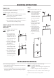
MOUNTING INSTRUCTIONS RM2351-2354 Snap in To mount the panel, follow these steps: We recommend to mount the panel on the door before the refrigerator is installed in the enclosure. 1. Open the door 90 degrees. 2. On new refrigerators, the decoration strip are taped inside the door; if installed on the door, remove the door decoration strip (2) by gently pushing the four tabs away with a flat blade screwdriver (1). 3. Insert the vertical edges into the grooves of the door frame (3). 4.
APPENDIX A - REARVIEW EQUIPMENT RM2351 Heater Flue baffle Drain water hose Power module cover Protection cover Screw for protection cover Burner jet 12 V DC Terminal block Manual gas shutoff valve Inlet fitting Flexible cord RM2354 Heaters Relay Flue baffle Drain water hose Power module cover Protection cover Screw for protection cover 12 V DC Terminal block Burner jet Manual gas shutoff valve Inlet fitting Flexible cord - 11 -
APPENDIX A - REARVIEW EQUIPMENT RM2451-2454-2551-2554 Heater Relay, 3-way only Flue baffle Power module cover Protection cover 12V DC Screw for protection cover Burner jet 12 volt Terminal block Manual gas shutoff valve Inlet fitting Drain water hose Flexible cord RM2652-2662-2663-2852-2862-3862-NDR1062 Heater(s) Relay, 3-Way only Thermofuse Flue baffle Power module cover Protection cover 12V DC Screw for protection cover 12 volt DC Terminal block Flexible cord Burner jet Drain water hose Inl
APPENDIX B - WIRING DIAGRAMS RM2351-2451-2551 RM2354-2454-2554 - 13 -
APPENDIX B - WIRING DIAGRAMS RM2652-2662-2852-2862 RM2663 - 14 -
APPENDIX B - WIRING DIAGRAMS RM3862 - NDR1062 (BS, SS)* NDR1062 (B)* * BS = Black stainless steel doors SS = Stainless steel doors B = Door insert panels - 15 -
TO THE INSTALLER PLEASE AFFIX THESE INSTRUCTIONS TO THE REFRIGERATOR — TO THE CONSUMER PLEASE RETAIN THESE INSTRUCTIONS FOR FUTURE REFERENCE