
User manual


BUILDING-IN
The refrigerator is intended for installation in a caravan or
motorhome, and the description relates to this application.
The refrigerator must not be exposed to radiated heat
from hot objects (e.g. below a cooker without proper heat
shielding).
Excessive heat irradiation impairs performance and leads
to increased energy consumption. For this reason the ref-
rigerator should be installed if possible not at the entrance
side of the vehicle - normally orientated south and often
with an awning - which would impair the dispersion
of heat and combustion gases from the ventilation
openings.
It is not a good practice to install the refrigerator so that
the vent openings are covered by the vehicle's entrance
door when this is open. This would reduce the ventilation
air flow to the cooling unit and reduce refrigeration
performance.
The Enclosure
The refrigerator must be installed in an enclosure, the
dimensions of which are shown in TECHNICAL DATA.
The bottom of the enclosure must be horizontal and even
so that the refrigerator can be easily pushed into place. It
must be sturdy enough to carry the wieght of the refrige-
rator.
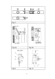
Battens must be installed at the enclosure and fitted with
sealing strips, as shown in fig. 4.
Slide in the refrigerator until it is flush with the front of the
recess. There must be 10-20 mm free space behind the
refrigerator.
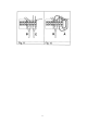
Four fasteners are fitted in plastic bushings in the side
walls of the fridge, fig. 7. They are used for securing the
refrigerator in the enclosure.
The side walls of the enclosure and/or any wooden bra-
ces installed to hold the refrigerator must be dimensioned
to seat the screws securely, also considering the forces
due to the movement of the vehicle.
With the refrigerator in place, drive the screws through
the bushings in the lining (fig.7) of the refrigerator into the
walls of the enclosure. There must not be more than 3mm
of clearance between refrigerator and enclosure on each
side. If necessary, wooden strips or similar should be
fitted.
Note: This is the only approved means of securing the
refrigerator to the enclosure and to the vehicle. Fasteners
penetrating other parts of the insulation (PU) foam of the
refrigerator might damage components like electric wiring
etc.
VENTILATION OF THE UNIT
At high ambient temperatures the refrigeration unit will
only perform adequately when properly ventilated.
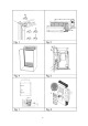
The refrigeration unit is ventilated via two openings in the
wall of the caravan (see fig. 5). Fresh air enters through
the lower opening and warm air is discharged through the
upper one.
Locate the lower opening immediately above the floor of
the recess, and the upper one as high as possible above
the condenser (C) of the refrigeration unit, at least as
shown in fig. 6b but preferably as shown in fig. 6a.
Ventilation grilles Fig. 2
The openings in the caravan wall must be fitted with the
Dometic ventilation systems.
Fitting the grilles, model L100/L200, which were specially
developed by Dometic for this purpose (shown as D in fig.
6). It is a good idea, to install the frame (A in the same
figure), at the same time. Then the grilles can be easily
removed which permits inspection and small repairs to be
carried out without the necessity for removing the refrige-
rator from the recess.
If there is no outer grille at floor level where leaking gas
can escape, a 40 mm hole to the outside should be made
in the floor of the recess to drain any unburnt gas to the
outside gas.
Fit the hole with wire mesh and an angled plate to protect
from stones, mud etc.
Removal of flue gases
The ventilation passage at the rear of the recess, bet-
ween the outer wall of the vehicle and the refrigerator (fig.
6), is sealed off against the living space, and so cold
draughts are excluded (winter camping) and no flue
gases can penetrate into the vehicle. Thus a special flue
outlet is no longer necessary - the gases are dispersed
through the upper vent grille.
Note: With this mode of installation the same type of gril-
les (without an integrated flue outlet), should be installed
at the upper as well as at the lower vent open-ning. The
angled T-piece for the flue tube (when delivered) should
not be used in this case.
The top of the enclosure above the flue tube (I), fig. 6,
should be covered with aluminum sheet metal, as indica-
ted in (B), to facilitate the heat dispersion.
In fig. 6 the letters have the following meaning:
A. Frame for the grilles
B. Aluminum cladding
C. Condenser of cooling unit
D. Vent grill
E. Sealing profile (optional extra)
Width 522 mm
F. Refrigerator rear wall
G. Wooden batten approx. 10 x 20
mm (see fig. 4)
H. Height of the enclosure
(see TECHNICAL DATA)
I. Flue tube
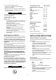
LP GAS CONNECTION
CHECK THAT THE GAS SUPPLIED TO THE REFRIGE-
RATOR IS AT THE CORRECT PRESSURE. LOOK AT
THE REDUCING VALVE ON THE LP GAS CONTAINER.
The refrigerator is designed for operation on LP gas of
Butane type the pressure of which must be 28 mbar for
Butane and 37 mbar for Propane.
The refrigerator is not designed for operation on town gas
or natural gas.
Check that this is stated on the data plate. The refri-
gerator is not designed for operation on town gas or
natural gas.
The gas installation should only be carried out by an
authorised gas fitter.
7
CAUTION