
User manual


The supply pipe should preferably be of copper. If any
other material is used, it must be of a type approved for
use with continuously operating bottled- gas appliances,
and have threaded compression connections throughout.
PUSH-ON CONNECTIONS MUST NOT BE USED (We
do not approve the use of "rubber" type flexible tubing for
connecting permanently operating appliances of this
type). All connectors etc. should be of a type specifically
designed for the type and diameter of the connection pipe
used, and screwed joints should be sealed with a joining
compound approved for use with bottled gas.
The gas supply pipe should be connected to the gas inlet
pipe on the right hand side of the gas control valve by
means of a suitable threaded compression coupling.
In making the connection to the refrigerator, a gas cock of
an approved type for use LPG must be incorporated in
the supply line in a position which is readily accessible to
the user. For eventual servicing purposes, the union
should be on the outlet side of the cock and the pipework
should be positioned so as not to prevent the
refrigerator from being readily withdrawn.
ELECTRICAL CONNECTION
The electrical installation must be carried out in a proper
and durable manner, taking into account all relevant regu-
lations and codes of practice. For mains voltage operati-
on, it is important that the circuit to and in the caravan is
effectively earthed.
ALL MAINS VOLTAGE WIRING IN THE CARAVAN
MUST BE INSTALLED IN ACCORDANCE WITH CUR-
RENT REGULATIONS .
For connection to a 120V electricity supply, the refrigera-
tor has a 3-core mains lead which is intended for connec-
tion to a properly earthed plug and socket outlet or fused
spur.
IMPORTANT: The wires in the mains lead of this applian-
ce are coloured in accordance with the following code:
GREEN-AND-YELLOW = EARTH
BLUE = NEUTRAL
BROWN = LIVE
As the colours of the wires may not correspond with the
coloured markings identifying the terminals in your plug,
proceed as follows:
The wire which is coloured GREEN-AND-YELLOW must
be connected to the terminal in the plug which is marked
with the letter E or by the earth symbol or
coloured green or green-and-yellow.
The wire which is coloured BLUE must be connected to
the terminal which is marked with the letter N or coloured
black.
The wire which is coloured BROWN must be connected
to the terminal which is marked with the letter L or colou-
red red.
WARNING! THIS APPLIANCE MUST BE EARTHED!
Electrical leads must be routed and secured so that
they cannot come into contact with hot or sharp parts
of the refrigerator.
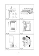
120 V Supplies
Check that the voltage stated on the data plate is the
same as the mains voltage in use (120V AC).
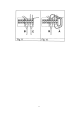
Diagram for the mains installation: fig. 9.
12 V Supplies
Connect the refrigerator to the vehicle battery by a direct
cable. To avoid a voltage drop, the cross sectional area of
the connecting cable between battery and refrigerator
must be at least 2.5 mm
2
if the distance is less than 9
meters, and at least 4 mm
2
if the distance is more than 9
meters.
To ensure satisfactory operation, the positive lead must
be fitted with a fuse rated at max. 16 A.
To prevent the refrigerator from draining the battery, make
sure that the current supplied to the caravan is cut off
when the vehicle engine is not running, for example by fit-
ting an ignition control relay.
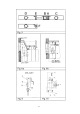
Diagram for the 12 V installation:
fig. 10 (RM 4180), fig.12 (RM4181)
The notations in the wiring diagram are:
A. Electronic igniter/reigniter
B. Electrode (at burner)
C. 12 V heating element
D. Switch for 12 V operation
E. Switch for reigniter (gas op.)
F. Electric thermostat
G. Heating element, 120 V
H. Switch for 120 V operation
J. Terminal block
L. Terminal block
12 V supply of reigniter (RM 4181)
Fig.12 shows the wiring diagram of the refrigerator as
delivered. The 12 V supply enters at (L). The reigniter (A)
is fed via two wires (1) and (2) at terminal block (L).
It is advisable to feed the reigniter and the lighting from a
separate 12 V source. To do this: remove the wires (1)
and (2) and connect the supply as is shown in fig. 11.
The reigniter should not be connected directly to a
battery charger but only over a battery.
DO NOT connect lights or any other electrical
components to the same circuit that is used by
the refrigerator.
8
CAUTION
CAUTION
CAUTION
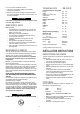
LP GAS
CYLINDER
PRESSURE
REGULATOR
TO
REFRIGERATOR