
User manual


● Remove the lower trim moulding and then withdraw the
panel by sliding it downwards.
● Fit new panel in place and slide it up as far as possible.
● Fit the trim moulding back in place.
B
UILDING-IN
T
he refrigerator is intended for installation in a caravan or
m
otorhome, and the description relates to this application.
T
he refrigerator must not be exposed to radiated heat from
h
ot objects (e.g. below a cooker without proper heat shiel-
d
ing).
E
xcessive heat irradiation impairs performance and leads to
i
ncreased energy consumption. For this reason the refrige-
r
ator should be installed if possible not at the entrance side
o
f the vehicle - normally orientated south and often with an
a
wning - which would impair the dispersion of heat and
c
ombustion gases from the ventilation openings.
I
t is not a good practice to install the refrigerator so that the
v
ent openings are covered by the vehicle's entrance door
w
hen this is open. This would reduce the ventilation air flow
t
o the cooling unit and reduce refrigeration performance.
T
he enclosure
T
he refrigerator must be installed in an enclosure, the
d
imensions of which are shown in TECHNICAL DATA.
T
he bottom of the enclosure must be horizontal and even
s
o that the refrigerator can be easily pushed into place. It
m
ust be sturdy enough to carry the wieght of the refrigera-
t
or.
B
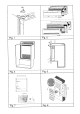
attens must be installed at the enclosure and fitted with
s
ealing strips, as shown in fig. 4.
S
lide in the refrigerator until it is flush with the front of the
r
ecess. There must be 10-20 mm free space behind the
r
efrigerator.
F
our fasteners are fitted in plastic bushings in the side walls
o
f the fridge, fig. 7. They are used for securing the refrigera-
t
or in the enclosure.
T
he side walls of the enclosure and/or any wooden braces
i
nstalled to hold the refrigerator must be dimensioned to
s
eat the screws securely, also considering the forces due to
t
he movement of the vehicle.
W
ith the refrigerator in place, drive the screws through the
b
ushings in the lining of the refrigerator into the walls of the
e
nclosure (fig.7). There must not be more than 3mm of
c
learance between refrigerator and enclosure on each side.
I
f necessary, wooden strips or similar should be fitted.
N
ote: This is the only approved means of securing the
r
efrigerator to the enclosure and to the vehicle. Fasteners
p
enetrating other parts of the insulation (PU) foam of the
r
efrigerator might damage components like electric wiring
e
tc.
V
ENTILATION OF THE UNIT
A
t high ambient temperatures the refrigeration unit will only
p
erform adequately when properly ventilated.
T
he refrigeration unit is ventilated via two openings in the
w
all of the caravan (see fig. 5). Fresh air enters through the
l
ower opening and warm air is discharged through the upper
o
ne.
L
ocate the lower opening immediately above the floor of the
r
ecess, and the upper one as high as possible above the
c
ondenser (C) of the refrigeration unit, at least as shown in
f
ig. 6b but preferably as shown in fig. 6a.
V
entilation grilles Fig. 2
T
he openings in the caravan wall must be fitted with the
E
lectrolux ventilation systems.
F
itting the grilles, model A 1620, which were specially
d
eveloped by Electrolux for this purpose (shown as D in fig.
6
). It is a good idea, to install the frame R 1640 (A in the
s
ame figure), at the same time. Then the grilles can be
e
asily removed which permits inspection and small repairs
t
o be carried out without the necessity for removing the
r
efrigerator from the recess.
I
f there is no outer grille at floor level where leaking gas can
e
scape, a 40 mm hole to the outside should be made in the
f
loor of the recess to drain any unburnt gas to the outside
g
as.
F
it the hole with wire mesh and an angled plate to protect
f
rom stones, mud etc.
R
emoval of flue gases
T
he ventilation passage at the rear of the recess, between
t
he outer wall of the vehicle and the refrigerator (fig. 6), is
s
ealed off against the living space, and so cold draughts are
e
xcluded (winter camping) and no flue gases can penetrate
i
nto the vehicle. Thus a special flue outlet is no longer
n
ecessary - the gases are dispersed through the upper vent
g
rille.
N
ote: With this mode of installation the same type of grilles
(
without an integrated flue outlet), should be installed at the
u
pper as well as at the lower vent open-ning. The angled
T
-piece for the flue tube (when delivered) should not be
u
sed in this case.
T
he top of the enclosure above the flue tube (I), fig. 6,
s
hould be covered with aluminum sheet metal, as indicated
i
n (B), to facilitate the heat dispersion.
I
n fig. 6 the letters have the following meaning:
A. Frame R 1640 for the grilles
B. Aluminum cladding
C. Condenser of cooling unit
D. Vent grill A 1620
E. Sealing profile (optional extra)
Width 486 mm, Electrolux art. nr. 295 1147-10
F. Refrigerator rear wall
G. Wooden batten approx. 10 x 20 mm (see fig. 4)
H. Height of the enclosure (see TECHNICAL DATA)
I. Flue tube
L
P GAS CONNECTION
T
he refrigerator is designed for operation on LP gas of
B
utane type the pressure of which must be 28 mbar for
B
utane and 37 mbar for Propane.
CAUTION! CHECK THAT THE GAS SUPPLIED TO
THE REFRIGERATOR IS AT THE CORRECT
PRESSURE. SEE THE REDUCING VALVE ON THE
LP GAS CONTAINER
11