
User manual


C
heck that this is stated on the data plate. The refrigerator
i
s not designed for operation on town gas or natural gas.
T
he gas installation should only be carried out by an
a
uthorized gas fitter.
T
he supply pipe should preferably be of copper. If any other
m
aterial is used, it must be of a type approved for use with
c
ontinuously operating bottled- gas appliances, and have
t
hreaded compression connections throughout. PUSH-ON
C
ONNECTIONS MUST NOT BE USED (We do not appro-
v
e the use of ``rubber'' type flexible tubing for connecting
p
ermanently operating appliances of this type in the United
K
ingdom). All connectors etc. should be of a type specifical-
l
y designed for the type and diameter of the connection pipe
u
sed, and screwed joints should be sealed with a joining
c
ompound approved for use with bottled gas.
T
he gas supply pipe should be connected to the gas inlet
p
ipe on the right hand side of the gas control valve by
m
eans of a suitable threaded compression coupling.
I
n making the connection to the refrigerator, a gas cock of
a
n approved type for use on LPG must be incorporated in
t
he supply line in a position which is readily accessible to
t
he user. For eventual servicing purposes, the union should
b
e on the outlet side of the cock and the pipework should
b
e positioned so as not to prevent the refrigerator from
b
eing readily withdrawn.
E
LECTRICAL CONNECTION
T
he electrical installation must be carried out in a proper
a
nd durable manner, taking into account all relevant regula-
t
ions and codes of practice. For mains voltage operation, it
i
s important that the circuit to and in the caravan is effec-
t
ively earthed. ALL MAINS VOLTAGE WIRING IN THE
C
ARA-VAN MUST BE INSTALLED IN ACCORDANCE
W
ITH CURRENT I.E.E. REGULATIONS INCLUDING THE
U
SE OF AN OUTLET AND COUPLER TO BS4343/-
C
EE17.
F
or connection to a 230 V electricity supply, the refrigerator
h
as a 3-core mains lead which is intended for connection to
a
properly earthed plug and socket outlet or fused spur.
I
MPORTANT: The wires in the mains lead of this appliance
a
re coloured in accordance with the following code:
G
REEN-AND-YELLOW = EARTH
B
LUE = NEUTRAL
B
ROWN = LIVE
A
s the colours of the wires may not correspond with the
c
oloured markings identifying the terminals in your plug, in
t
he United Kingdom, proceed as follows:
T
he wire which is coloured GREEN-AND-YELLOW must be
c
onnected to the terminal in the plug which is marked with
t
he letter E or by the earth symbol or coloured green or
g
reen-and-yellow.
T
he wire which is coloured BLUE must be connected to the
t
erminal which is marked with the letter N or coloured black.
T
he wire which is coloured BROWN must be connected to
t
he terminal which is marked with the letter L or coloured
r
ed.
I
n the United Kingdom, the plug or circuit to the refrigerator
m
ust be fitted with a fuse not greater than 5 amps. If a 13
a
mp.(B.S.1363) fused plug is used, it should be fitted with a
3
amp. fuse. In other countries, the fuse rating will depend
u
pon the voltage and local practice.
2
30 V Supplies.
C
heck that the voltage stated on the data plate is the same
a
s the mains voltage in use (230 V).
1
2 V Supplies
C
onnect the refrigerator to the vehicle battery by a direct
c
able. To avoid a voltage drop, the cross sectional area of
t
he connecting cable between battery and refrigerator must
b
e at least 2.5 mm
2
if the distance is less than 9 meters,
a
nd at least 4 mm
2
if the distance is more than 9 meters
T
o ensure satisfactory operation, the positive lead must be
f
itted with a fuse rated at max. 16 A.
T
o prevent the refrigerator from draining the battery, make
s
ure that the current supplied to the caravan is cut off when
t
he vehicle engine is not running, for example by fitting an
i
gnition control relay.
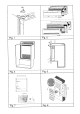
Diagramme for the mains installation: fig. 9
Diagramme for the 12 V installation:
fig. 10 (RM 4270), fig. 12 (RM 4271)
T
he notations in the wiring diagramme are:
A. Electronic igniter/reigniter
B. Electrode (at burner)
C. 12 V heating element
D. Switch for 12 V operation
E. Switch for reigniter (gas op.)
F. Electric thermostat
G. Heating element, 230 V
H. Switch for 230 V operation
J. Terminal block
L. Terminal block
1
2 V supply of reigniter (RM 4271)
F
ig. 12 shows the wiring diagramme of the refrigerator as
d
elivered. The 12 V supply enters at (L). The reigniter (A) is
f
ed via two wires (1) and (2) at terminal block (L).
I
t is advisable to feed the reigniter and the lighting from a
s
eparate 12 V source. To do this: remove the wires (1) and
(
2) and connect the supply as is shown in fig. 11.
I
n some executions there in an extra terminal block (J), of
f
ig. 12. In this case one disconnects the wires as said above
b
ut connects the separate supply to (J).
T
he reigniter should not be connected directly to a battery
c
harger but only over a battery.
Electrical leads must be routed and secured so that
they cannot come into contact with hot or sharp parts
of the refrigerator.
WARNING! THIS APPLIANCE MUST BE EARTHED !
12