MANUAL ABSORPTION - REFRIGERATOR for RECREATIONAL VEHICLES RM 6290 (L) RM 6291 (L) RM 6401 (L) RM 7270 (L) RM 7290 (L) RM 7360 (L) RM 7370 (L) RM 7400 (L) RM 7540 (L) RM 7550 (L) EN Please state for future reference : Model number ............................................. Product number ............................................. Serial number ............................................. OPERATING INSTRUCTIONS INSTALLATION INSTRUCTIONS English Type C40 / 110 T.B.
Dansk Deutsch Ελληνικά English Español Français via INTERNET www.dometic.
TABLE OF CONTENTS 1.0 2.0 Information 3.0 4.0 5.0 INTRODUCTION FOR YOUR SAFETY 4 4 2.1 Warning and safety notices 4 2.2 Coolant 4 WARRANTY AND CUSTOMER SERVICE 5 3.1 5 DESCRIPTION OF MODEL REFRIGERATOR GUIDE 5.1 5.2 5.3 5.4 5.5 5.6 5.7 5.8 5.9 5.10 5.11 5.12 5.13 5.14 5.15 5.16 5.17 5.18 5.19 5.20 6.
1.0 INTRODUCTION You have made an excellent choice in selecting the Dometic Absorption Refrigerator. We are sure that you will be fully satisfied with your new appliance in all respects. The appliance, which works silently, meets high quality standards and guarantees the efficient utilisation of resources and energy throughout its entire life cycle, during manufacture, in use and when being disposed of.
3.0 WARRANTY AND CUSTOMER SERVICE Warranty arrangements are in accordance with EC Directive 44/1999/CE and the normal conditions applicable for the country concerned. For warranty or other servicing, please contact our Dometic Service department. Any damage due to improper use is not covered by the warranty.
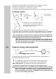
5.2 Using the refrigerator The cooling unit is silent in operation. When the appliance is first put into operation, there may be a mild odour which will disappear after a few hours. Ensure the living area is well ventilated. The freezer compartment should be cold about one hour after switching on the refrigerator. The refrigerator will take several hours to reach its operating temperature. 5.2.1 Controls A. Manual Ignition “Piezo” (e.g.
5.2.2 Electrical operation 1. 12V DC The refrigerator should only be used while the motor is running. 1. Set energy selector switch (A) to. A The refrigerator operates without thermostatic control (continuous operation). 2. Mains power This option should only be selected where the supply voltage of the connection for power supply corresponds to the value specified on the data plate. Any difference in values may result in damage the appliance. 1. Set energy selector switch (A) to. A 5.2.3 B 2.
5. 6. 7. 8. Keep rotary switch (B) depressed for another 10-15 seconds, then release. Check the inspection glass to see whether a flame is burning. Repeat the entire process if the flame has gone out. Use rotary switch (B) to regulate the temperature in the main refrigerator compartment. 2. Automatic ignition A B 1. Set energy selector switch (A) to Gas. D 2. Press and hold rotary switch (B). 3.
5.3 Storing food Switch the refrigerator on approx. 12 hours before filling it. Always store pre-cooled foods in the refrigerator. Make sure that the food is well cooled when it is bought and also when transporting it. Use insulated cooling bags. When taking food out of the refrigerator only open the refrigerator door very briefly. Foods must be packed - best of all in closed containers, aluminium foil or similar and stored separately from each other.
5.6 Door locking close open RM 6xxx park position RM 7xx0 open 5.7 park position close Switching off 2. Secure the door open by means of the door stop. The door will be slightly ajar; this is to prevent mould from forming inside the appliance. A 1. Set energy selector switch (A) to position "0" (OFF). The appliance is now fully switched off.
5.9 Winter operation 1. Check that the ventilation grilles and the extractor have not been blocked by snow, leaves or similar. Lower ventilation grille ( L200 ) Upper ventilation grille with flue vent ( L100) 2. When the ambient temperature falls below +8°C, the optional winter covers should be fitted. This protects the unit from excessively cold air. 3. Affix the cover and fasten it.
5.11 Changing the decor panel 1. Open the door and loosen the hinge screw. 4. Remove the decor plate and insert a new decor plate. 2. Take off the door by moving it upwards. 5. Screw the door strip back in position. 3. Unscrew the door strip (3 screws). 6. Put the door back on.
5.12 Changing the doorhang It is not always possible to change the door when the refrigerator is installed. 1. Open the door, unscrew the hinge screw and keep it to hand. 2. Take off the door by moving it upwards. (example RM 6xx1) 6. 5. 4. 5. 7. 4. 3. 8. 9. Attach the door. 10. Screw the hinge screw back in.
5.13 Troubleshooting Before calling the authorised Service Department, please check whether: 1. The instructions in the section "Using the refrigerator" have been followed. 2. The refrigerator is not tilted excessiveley. 3. It is possible to operate the refrigerator with an available power source. Failure : The refrigerator does not work in gas operation mode. Possible cause Action you can take a.) Gas bottle empty. a.) Change gas bottle. b.) Is the supply cut-out device open? b.
5.14 Maintenance Works on gas components and electical installation may only be carried out by authorised personnel. We recommend to contact your Dometic Service Centre. EN 1949 stipulates that the appliance´s gas equipment and it’s associated fume system must be inspected after installation and a certificate issued. Afterwards a qualified technician must inspect according to EN 1949 every two years and a certificate issued. It is the user’s responsibily to arrange for inspections after purchase.
5.19 Technical data Model Dimensions H x W x D (mm) depth incl. door Groos capacity Usable Connection incl. freezer capacity of Mains / Battery compartment freezer compartment * Consumption electricity / gas in 24 hrs Netweight Ignition Ignition Piezo Reigniter RM 6290(L) 821x525x541 RM 6291(L) 821x525x541 RM 6401(L) 821x525x541 86 lit. 86 lit. 97 lit. 10,5 lit. 10,5 lit. 10,5 lit. 125 W / 120 W 125 W / 120 W 135 W / 130 W ca.2,5 KWh / 270 g ca.2,5 KWh / 270 g ca.
6.0 INSTALLATION GUIDE On installation of the appliance, the technical and administrative regulations of the country in which the vehicle will first be used must be adhered to. Otherwise the refrigerator must be installed as described in these instructions. In some OEM applications it may not be possible for these instructions to be followed exactly.
6.2 Draught-free installation The refrigerator must be sealed in accordance with EN 1949. Do NOT use any easily inflammable materials (in particular silicone sealing agent or similar) for sealing! The device manufacturer's product liability and guarantee shall lapse if such materials are used. Illustrated below are two typical approved methods of sealing. Proposal 1: Using the Installation Sealing Kit from Dometic (SP.No.
In this case, for gas operation, do not use the upper winter cover! If even with draught-free installation a fume chimney is desirable, you must incorporte the L100 ventilation and extraction system into the upper air vent opening. Installation of fume chimney: please refer to point 6.7. Deviations shall require the consent of the manufacturer. 6.
6.4 Installing the ventilation system L 200 L 100 To install the ventilation grilles, cut two rectangles (451mm x 156mm) in the outer wall of the vehicle (for position of the cuts, see point 6.3). Item 1 does not apply for installation framess with an integrated seal. 1. Seal the mounting frame, making it waterproof. 2. Insert the frame ... ... and screw into position. 3. Insert the ventilation grilles. 4. Lock the ventilation grilles.. 5.
6.5 Installation recess The refrigerator must be installed draught-free in a recess. The measurements of the recess are given in the table below. Step (A) is only required for cabinets with a step. Push the appliance far enough into the recess until the front edge of the refrigerator casing is flush with the front of the recess. Allow a gap of 15-20 mm between the back wall of the recess and the refrigeration unit.
6.7 Fume extraction Fume extraction must be arranged in such a way as to provide complete extraction of all products of combustion to an area outside the living area. The flue system must slope in an upward direction in order to avoid a build-up of condensation. An installation that is not carried out by qualified persons causes a reduction in the cooling capacity and will jeopardize the manufacturer's guarantee. 6.7.1 Fitting the fume flue in the upper ventilation grille min. 10 mm max. 20 mm 4.
6.7.2 Separate fume extraction min. 10 mm max. 20 mm Cut: 80mm high 40mm wide 1. Cut an 80mm x 40mm rectangle in the outer wall of the caravan. The position of the cut must be appropriate to the particular model of refrigerator and installation conditions. 2. Connect T-piece (E) to adaptor (F) or flue pipe (K) as required and affix with screw (G). Ensure that heat distributor (H) is lodged in the correct position. 3. Insert flue pipe (C) through the aperture. 4. Connect flue pipe (C) to T-piece (E).
The gas connection to the appliance is effected by means of a suitable coupling tube fitting L8, DIN 2353-ST, complying with European Standard EN 1949 (e.g. Ermeto). The gas connection may only be carried out by a qualified personnel. SW 14 SW 17 Following proper installation, a testing for leakage and a flame test must be carried out by *qualified personnel in compliance with EN1949 . A certificate of testing must be issued.
6.9 Electrical installation Electrical installation may only be carried out by qualified personnel. The connection cables must be laid in such a way that they do not come in contact with hot components of the unit/burner or with sharp edges. The electrical installation must comply with national regulations (EN 60335-2-24 for Europe). It is advisable to run the incoming supply through an on-board fuse or automatic circuit breaker.
6.9.3 Wiring diagrams 1. Wiring diagram with manual ignition and no interior light. mains connection AC battery connection DC heatingelement DC thermo cut-off current heatingelement AC 2.
3. Wiring diagram with automatic ignition and no interior light reigniter battery connection 12V/24V -- spark plug ground ignition control lamp heating-element DC - Battery connection 12V/24V A = Ground heating element DC, white B = Heating element DC-, red C = Ground automatic ignition, black D = Automatic ignition violet to casing mains connection ~ thermo cut-off current from battery to casing to casing heatingelement AC~ 4.
Dometic GmbH In der Steinwiese 16 D-57074 Siegen www.dometic.de/caravan www.dometic.