Foreword This service manual is the result of the dedication of The Dometic Corporation and its engineers in giving service people the necessary instruction for making accurate analyses of certain conditions. Provided is a diagnostic chart leading a qualified mechanic into the service manual pages to locate and solve symptoms which may occur. Dometic has continued its commitment in providing service people with this, the most up-to-date information about servicing Dometic RV accessories. . form No.
DIAGNOSTIC SERVICE MANUAL CONTENTS DOMETIC® RM7030/RM7732 Refrigerators PAGE NO. RM7030/RM7732 DIAGNOSTIC FLOW CHART ........................... 1 SECTION 1 OPERATION 1.1 RM7030 (Prod. #921890201 & 921890301) Refrigerator Operation .......................................................... 5 1.2 RM7030 (Prod. #921890401) Refrigerator Operation ................ 6 1.3 RM7732 Refrigerator Operation ............................................. 7 SECTION 2 AC VOLTAGE AC Voltage Requirements ............
DOMETIC® RM7030/RM7732 Refrigerators CONTENTS DIAGNOSTIC SERVICE MANUAL PAGE NO. SECTION 8 WIRING 8.1 8.2 External Wiring .................................................................. 21 Internal Wiring ................................................................... 21 SECTION 9 OTHER 9.1 9.2 9.3 9.4 9.5 9.6 9.7 9.8 9.9 Leveling ............................................................................ 25 Ventilation ........................................................................
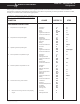
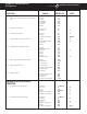
DOMETIC® RM7030/RM7732 Refrigerators DIAGNOSTIC SERVICE MANUAL This program will address the most common system problems associated with the Dometic RM7030/RM7732 refrigerators supplied by The Dometic Corporation. Our intent is to provide you with a guideline of checks to make, should you encounter one of the following symptoms. RM7030 REFRIGERATOR SECTION: Product No. 921890201 & 921890301 SYMPTOM CAUSE REFER TO STEP REFRIGERATOR SECTION 1. 2. 3. 4. 5. 6. 7.
DOMETIC® RM7030/RM7732 Refrigerators SYMPTOM CAUSE REFER TO STEP 8. Insufficient cooling on gas cools properly on AC. LP Gas Orifice Flue Baffle Flue Tube Flue Cap Burner 6 7.2 7.5 7.7 7.6 7.4 9. Freezes on all modes. Thermostat DC volts 5.1 4 DC Volts Wiring Lower Circuit Board 4 8.1 5.9 A 11. Flame failure light within 10 seconds. Igniter High Voltage Cable Electrode Wiring 5.5 5.6 5.11 8.2 A A 12. Flame failure light after 3 minutes.
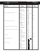
DOMETIC® RM7030/RM7732 Refrigerators DIAGNOSTIC SERVICE MANUAL SYMPTOM 18. No AC operation operates on gas. CAUSE REFER TO STEP Operation AC Volts Fuse Heating Element Upper Circuit Board Wiring Lower Circuit Board 1.1B or 1.2 2 5.7 3 5.8 8.2 5.9 Operation LP gas Manual Gas Valve Igniter High Voltage Cable Electrode Solenoid Upper Circuit Board Wiring Lower Circuit Board 1.1B or 1.2 6 7.1 5.5 5.6 5.11 5.4 5.8 8.2 5.9 20. Insufficient cooling on all modes.
DOMETIC® RM7030/RM7732 Refrigerators SYMPTOM CAUSE REFER TO 26. Interior light on when door is closed. Wiring Door Switch Door Position 8.2 5.10 9.4 27. Rapid formation of frost. Food Storage Interior Liner to Frame High Humidity Air Leaks 9.7 9.9 9.8 9.3 28. Water on frame. Interior Liner to Frame High Humidity Air leaks Climate Control Heater 9.9 9.8 9.3 5.12 29. Ice Maker fails to start. Operation Arm in UP Position AC Voltage Water Valve Ice Maker Cycle 10 11.4 2 11.7 11.8 30.
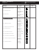
DOMETIC® RM7030/RM7732 Refrigerators DIAGNOSTIC SERVICE MANUAL SECTION 1 1.1 OPERATION RM7030 (Product No. 921890201 & 921890301) A B C OFF D ON E F G H AC LP GAS ONLY OPERATION Turn switch "C" to the "ON" position and press pushbutton "B". The green indicator lamp over push-button "B" will come on and the refrigerator will operate only on LP gas even if 120 volts are available.
DOMETIC® RM7030/RM7732 Refrigerators FLAME FAILURE DURING LP GAS OPERATION If the LP gas flame fails during the burner cycle, the high voltage spark will continue arcing for up to three minutes. At the end of three minutes the gas control will stop the flow of LP gas to the burner, the sparking will stop and the red indicator lamp "H" will light up. LP gas operation will not be possible as long as this indicator is ON.
DOMETIC® RM7030/RM7732 Refrigerators DIAGNOSTIC SERVICE MANUAL 3. Press the TEMPERATURE SELECTOR button (3) until the lamp at the desired position is illuminated. 4. When operating in the AES mode, the AES mode indicator lamp "B" will illuminate. The control system will automatically select between AC and GAS operation with AC having priority over GAS. Either the AC indicator lamp "A" or the GAS indicator lamp "C" will illuminate depending on the energy source selected by the control system.
DOMETIC® RM7030/RM7732 Refrigerators GAS MODE Move the AUTO mode selector button (2) to the UP position. The GAS mode indicator lamp (C) will illuminate. After 45 seconds the burner should be ignited and operating normally. On the initial refrigerator start-up, it may take longer than 45 seconds to allow air to be purged from the gas line. If the gas does not ignite within 45 seconds, the CHECK indicator lamp (D) will illuminate and the GAS mode indicator lamp (C) will go off.
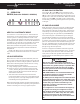
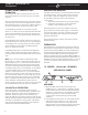
DOMETIC® RM7030/RM7732 Refrigerators DIAGNOSTIC SERVICE MANUAL SECTION 2 AC VOLTAGE REQUIREMENTS The refrigerator is a 120 volt AC, 60 Hz appliance. The proper operating range is 100 to 132 volts. Check the AC volts at the receptacle where the refrigerator is attached. If voltage is outside of the proper operating range, correct the power source problem. On RM7030 (Product No. 921890401) and RM7732, if voltage drops below 100 volts, cooling efficiency will decrease with voltage decrease.
DOMETIC® RM7030/RM7732 Refrigerators DIAGNOSTIC SERVICE MANUAL 5.2 THERMISTOR RM7030 (Prod. No. 921890401) and RM7732 To determine if the temperature sensor is functioning properly, perform the following test. Remove the cover from the lower circuit board. Disconnect the thermistor harness from the P2, 2-pin terminal on the lower circuit board. Place thermistor in a glass of ice water. Wait 2 to 3 minutes. Using an ohm meter, place a probe on each terminal point.
DIAGNOSTIC SERVICE MANUAL Next, hook up a manometer at the test port. Then check for DC volts at gas valve terminals while the unit is in trial-for-ignition. If DC volts are present and pressure is low, replace the valve. If DC volts are not present at the valve while unit is in trial-for-ignition, verify that the wires at Plug 3, Terminal 1 and 2 on lower circuit board have DC volts (9 or more). If the valve chatters, check for low input voltage to the valve (below 9V DC). 5.5 IGNITER A.
DOMETIC® RM7030/RM7732 Refrigerators DIAGNOSTIC SERVICE MANUAL 5.7 FUSES A. RM7030 (Product No. 921890201 & 921890301) The fuse is to protect the circuit board. To check the fuse, remove it from the holder and do a continuity check. If no continuity, replace it with a proper 3-amp time delay fuse. B. RM7030 (Product No. 921890401) and RM7732 The fuses are to protect the circuit board and the integrity of the heater circuit(s) against shorts.
DOMETIC® RM7030/RM7732 Refrigerators DIAGNOSTIC SERVICE MANUAL B. AES FUNCTION SWITCH NOTE: The following checks should be made on the upper circuit board and harness assembly BEFORE replacing the upper circuit board or wiring harness. The checks are to be done with the wiring harness REMOVED from the lower circuit board, and the ONOFF switch turned to "ON".
DOMETIC® RM7030/RM7732 Refrigerators DIAGNOSTIC SERVICE MANUAL With the mode switch (?) NOT depressed: A reading would NOT be indicated. NOTE: If the check on AC mode lamp and switch is not correct, verify the wire harness has continuity. If wire harness is good, replace the upper circuit board. G. DELAY MODE LAMP AND SWITCH NOTE: The following checks should be made on the upper circuit board and harness assembly BEFORE replacing the upper circuit board or wiring harness.
DOMETIC® RM7030/RM7732 Refrigerators DIAGNOSTIC SERVICE MANUAL With main ON/OFF switch on display panel in ON position: Check for DC volts between terminal 3 (red wire), () negative and terminal 5 (green wire) and terminal 1 (black wire). If there is no voltage, the ON/OFF switch on upper circuit board is defective. Replace the upper circuit board. If voltage is present, the ON/ OFF switch is good. Next, do the same voltage test at the lower circuit board.
DOMETIC® RM7030/RM7732 Refrigerators DIAGNOSTIC SERVICE MANUAL B. AC OPERATION THESE PROCEDURES MUST BE FOLLOWED IN SEQUENCE AND AT THE PROPER TERMINALS OR DAMAGE TO THE BOARD WILL RESULT. For AC heating element operation, check that voltage is present between the large black and large white wire at the circuit board. If voltage is below 100 volts, the circuit board will select another mode. If voltage is above 100 volts, check that AC volts are present at the heating element connection.
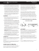
DOMETIC® RM7030/RM7732 Refrigerators DIAGNOSTIC SERVICE MANUAL Check for voltage at the heating element connection terminals J7 and J8 on the circuit board. If no voltage is present, check the 5 amp AC and 3 amp DC fuses. If fuse is defective, replace the fuse. If fuses are good, replace the circuit board. Black 3 Open 2 Green 1 6 Brown 5 Red 4 Orange or White Open 3 Blue 4 1 White P3 2 Yellow Repeat this test several times. If the igniter fails to spark on any test sequence, it should be replaced.
DOMETIC® RM7030/RM7732 Refrigerators 5.11 ELECTRODE First, do a visual check for cracks or breaks on the ceramic insulator. ELECTRODE Verify the TIP mounting 3/16" bracket is attached properly to the elecBURNER trode. If either of the above is found, replace the electrode. The spark gap must be set at three sixteenths (3/16") of an inch and tip of electrode above the slots in the burner. If igniter (see Sec. 5.5A or B) and high voltage cable (see Sec. 5.
DIAGNOSTIC SERVICE MANUAL DOMETIC® RM7030/RM7732 Refrigerators SECTION 7 LP GAS COMPONENTS 7.1 MANUAL GAS Shutoff VALVE The manual gas shutoff valve is where the incoming LP gas supply is attached. To check the shutoff valve, remove and inspect for any obstructions. The valve must be turned to "ON" before any gas operation can occur. RM7030 (Product No. 921890201 & 921890301) MANUAL GAS Shutoff VALVE RM7030 (Product No.
DOMETIC® RM7030/RM7732 Refrigerators DIAGNOSTIC SERVICE MANUAL 7.2 ORIFICE The orifice is a small brass fitting that has a ruby membrane that is laserbeam drilled and is mounted on the gas line just prior to the burner. The orifice is cleaned by using an alcohol based solvent and allowing to air dry. NEVER USE A DRILL BIT OR JET TIP CLEANER TO CLEAN ANY ORIFICE AS THESE DEVICES WILL DAMAGE THE FACTORY MACHINED PART AND CREATE A POTENTIALLY DANGEROUS CONDITION.
DOMETIC® RM7030/RM7732 Refrigerators DIAGNOSTIC SERVICE MANUAL 7.4 BURNER The burner is a slotted metal tube located below the flue tube on the cooling unit. It should be level, and the slots in the burner should be directly below the flue tube. The burner should be cleaned periodically, at least once a year. To clean the burner, remove from the refrigerator and check for any foreign residue that could cause a deflection of the gas flow or the flame.
DOMETIC® RM7030/RM7732 Refrigerators DIAGNOSTIC SERVICE MANUAL TYPICAL WIRING DIAGRAM FOR RM7030 (PRODUCT NO.
DOMETIC® RM7030/RM7732 Refrigerators DIAGNOSTIC SERVICE MANUAL TYPICAL WIRING DIAGRAM FOR RM7030 (PRODUCT NO.
DOMETIC® RM7030/RM7732 Refrigerators DIAGNOSTIC SERVICE MANUAL RM7732 TYPICAL WIRING DIAGRAM 24
DOMETIC® RM7030/RM7732 Refrigerators DIAGNOSTIC SERVICE MANUAL SECTION 9 OTHER 9.1 LEVELING In an absorption refrigerator system, ammonia is liquefied in the finned condenser coil at the top of the refrigerator. The liquid ammonia then flows into the evaporator (inside the freezer section) and is exposed to a circulating flow of hydrogen gas, which causes the ammonia to evaporate, creating a cold condition in the freezer.
DOMETIC® RM7030/RM7732 Refrigerators RM7732: SECURING THE REFRIGERATOR: After the refrigerator is mounted in place (ensuring a combustion seal at the front frame), the refrigerator is to be secured in the enclosure with six screws. The screws have to be installed in the following order: DIAGNOSTIC SERVICE MANUAL B. Carefully tilt the top decoration panel and lift up to remove from top frame. See FIG. 9. FIG.
DIAGNOSTIC SERVICE MANUAL 9.4 DOOR POSITION The door position can be checked by observing any misalignment of the door in relation to the frame. SMOOTH FIT, PROPER SEAL DOMETIC® RM7030/RM7732 Refrigerators place a thermometer in one of the containers of water. Next, supply 115 volts directly to the AC heating elements and operate for at least 12 hours. Then check the temperature on the thermometer. It should be at 45 degrees or lower depending on test conditions (see Sec. 9.2 and 9.5).
DOMETIC® RM7030/RM7732 Refrigerators 9.9 INTERIOR LINER SEAL TO FRAME There is a seal that is applied to the liner in the area where the metal frame makes contact with the interior liner. If this seal is incomplete, cold air can migrate out to the metal frame. If this happens, condensation could form on the frame and could promote rapid formation of frost. If you suspect an improper seal, apply a small bead of silicone all the way around the perimeter where the frame meets the interior liner.
DOMETIC® RM7030/RM7732 Refrigerators DIAGNOSTIC SERVICE MANUAL SECTION 10 SECTION 11 ICE MAKER OPERATION ICE MAKER COMPONENTS The refrigerator must be allowed to precool properly before starting the ice maker. The refrigerator has to be connected to 120 volts AC before the ice maker can operate. The water line manual shutoff valve must be open. To start making ice, move the ice level bail arm to DOWN position.
DOMETIC® RM7030/RM7732 Refrigerators 11.4 SHUTOFF ARM The shutoff arm is cam driven. It operates a switch to control the quantity of ice produced. During the ejection cycle the arm is raised and lowered during each of the two revolutions of the timing cam. If the shutoff arm comes to rest on top of the ice in the storage bin during either revolution, the switch will remain open and stop the ice maker at the end of that revolution.
DIAGNOSTIC SERVICE MANUAL 11.8 ICE MAKER ASSEMBLY It may be necessary to replace the entire ice maker assembly. Disconnect power to the appliance. Disconnect the leads inside the ice maker unit. Check each wire for continuity to make sure the wiring is good before replacing the ice maker unit. If there is no continuity on any of these wires, replace or repair them as necessary and recheck the ice maker unit to determine whether the problem was in the wiring or the unit itself.
DOMETIC® RM7030/RM7732 Refrigerators 32 DIAGNOSTIC SERVICE MANUAL
DIAGNOSTIC SERVICE MANUAL DOMETIC® RM7030/RM7732 Refrigerators 33
DOMETIC® RM7030/RM7732 Refrigerators DIAGNOSTIC SERVICE MANUAL SECTION 12 ICE MAKER OTHER 12.1 WATER FILL ADJUSTMENT The correct water level in the mold is important for the proper production of ice. The size of the ice cubes depends on the amount of water which enters the mold. The cubes should be approximately 1/2" wide, 3/4" high and 2-1/2" long. If the water overflows in the mold, first check to see if the ice maker unit is level in the appliance.
DIAGNOSTIC SERVICE MANUAL DOMETIC® RM7030/RM7732 Refrigerators 12.2 WIRING Refer to the wiring diagram supplied with the unit you are working on, and make sure all wiring connections are correct and tight. THIS IS AN ENERGIZED CIRCUIT. ELECTRICAL SHOCK CAN OCCUR. BEFORE CHECKING THESE COMPONENTS BE SURE THERE IS NO POWER TO THE APPLIANCE. ICE MAKER TYPICAL WIRING DIAGRAM 12.3 WATER SUPPLY To operate properly, the water pressure in the water supply line must be between 15 lbs. PSI and 125 lbs. PSI.