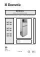
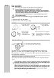
MANUAL INSTALLATION INSTRUCTIONS ABSORPTION REFRIGERATOR + OVEN for CARAVAN AND MOTORHOME RMT 7650 RMT 7850 RMT 7651 RMT 7851 RMT 7655 RMT 7855 Please state for future reference : Model number ............................................. Product number ............................................. Serial number ............................................. EN English Typ C40 / 110 T.B.
Dansk Deutsch Ελληνικά English Español Français via INTERNET www.dometic.
TABLE OF CONTENTS 1.0 2.0 Information INTRODUCTION ................................................ 4 FOR YOUR SAFETY ......................................... 4 2.1 2.2 3.0 Cleaning .................................................................. Using the refrigerator ............................................ Storing food ............................................................ Making ice cubes ................................................... Defrosting ...................................
1.0 INTRODUCTION You have made an excellent choice in selecting the Combined Absorption Refrigerator and Gas Baking Oven from Dometic. We are sure that you will be fully satisfied with your new appliance in all respects. The appliance, which works silently, meets high quality standards and guarantees the efficient utilisation of resources and energy throughout its entire life cycle, during manufacture, in use and when being disposed of.
2.2 Coolant Ammonia is used as a coolant. This is a natural compound also used in household cleaning agents (1 litre of Salmiak cleaner contains up to 200g of ammonia - about twice as much as is used in the refrigerator). Sodium chromate is used for corrosion protection (1.8% of the solvent). In the event of leakage (easily identifiable from the unpleasant odour): Switch off the appliance. Air the room thoroughly. Inform the authorised Customer Service department. 3.
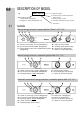
4.0 DESCRIPTION OF MODEL RMT 7651 L e.g. “L” with interior light “0” manual energy selection and manual ignition “Piezo” “1” manual energy selection “5” automatic and manual energy selection “RM” Refrigerator Mobil / Mobile Absorber Refrigerator “T” Refrigerator combined with baking oven “5” curved door 4.
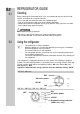
5.0 5.1 REFRIGERATOR GUIDE Cleaning Before switching the refrigerator on to use it, we recommend that you clean it inside and out, and repeat this at regular intervals. Use a soft cloth and lukewarm water with a mild detergent. Then rinse the appliance with clean water and dry thoroughly. Remove dust from the refrigerator unit at yearly intervals using a brush or soft cloth. (accessable through upper vent grille).
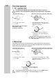
5.2.1 Electrical operation 1. 12V - operation (DC) The refrigerator should only be used while the motor is running, otherwise the on-board-battery would be discharged within a few hours! RMT 7650 / RMT 7850 RMT 7651 / RMT 7655 / RMT 7851 / RMT 7855 A A C 1. Set energy selector switch “A” to 12V. Operating display “C”, 12V lights “green”. Appliance is in function. 1. Set energy selector switch “A” to 12V. The refrigerator operates without thermostatic control. (continuous operation) B 2.
5.2.2 Gas operation The refrigerator should only be operated using liquid gas (propane, butane). Do not use town gas or natural gas. If the refrigerator is operated during travel using gas, the precautions stipulated by the legislation in the respective country must be taken (in conformity with the European standard EN 732). Operating the refrigerator with gas is not permitted during travel in France and Australia. As a basic rule, operation using gas is prohibited in petrol stations. 1.
5.2.3 “AUTO”-operation ( AES only ) RM7XX5 L - models are equipped with an “AUTO”-MATIC function. 1. Set energy selection switch “A” to position “AUTO”. The LED “AUTO” lights “green”. Manual operation is possible at any time. Explanations: Upon switching on, the electronics automatically select one of the three possible energy types: 230V - 12V - liquid gas. The control electronics automatically ensure that the refrigerator is supplied with the optimum source of energy in each respective case.
5.2.4 Gas faults (MES and AES) C A If gas faults occur the operating LED “C” flashes yellow. Remedies: Set the energy selector switch “A” to position “OFF”. 1. Is there any gas in the gas bottle? 2. Is the gas bottle valve open? 3. Is the on-board shut-off valve open? If point 1 to 3 is ok proceed with point 4 . 4. Set the energy selector switch “A” to position “AUTO” again. The ignition starts once more.
5.2.7 Temperature setting cooling compartment B As shown, you are able to regulate the temperature of the cooling compartment, if necessary, by turning rotary knob (B). medium setting The cooling unit’s performance is influenced by ambient temperatures. Please select the medium setting for ambient temperatures between TIP +15°C and +25°C. The unit operates within its optimum performance range. Dometic refrigerators work according to the absorption principle.
5.4 Making ice cubes Ice cubes are best frozen overnight. At night, the refrigerator has less work to do and the unit has more reserves. 1. Fill the ice cube tray with drinking water. 2. Place the ice cube tray in the freezer compartment. Only use drinking water! 5.5 Defrosting As time goes by, frost builds up on the fins. When the layer of frost is about 3mm thick, the refrigerator should be defrosted. 1. Switch off the refrigerator, as described in Section 5.8 - "Switching off". 2.
5.7 Door locking open 5.8 closed Switching off A 1. Set energy selector switch (A) to position "0". The appliance is now fully switched off. 2. Secure the door open by means of the door stop. The door will be slightly ajar. This is to prevent mould from forming inside the appliance. Switching off gas operation If the refrigerator is to be taken out of service for an extended period of time, the on-board shut-off valve and the cylinder valve must be closed. 5.
5.10 Interior light Changing the light bulbs 1. 2. 1. Remove cover. 90° 2. Detach defective light bulb. 3. Fit new light bulb Note: For 12V DC : 1 light bulb 12V, 2W 4. Clip the cover back in place. 5.11 Please contact Dometic Service Centres for replacement light bulbs. Changing the decor panel RMT 7X50 1.
5.12 Changing the doorhang It is not always possible to change the door when the refrigerator is installed. A RMT 7X50 RMT 7X51 RMT 7X55 1. Remove rotary knobs and unscrew control panel. Open the freezer door, unscrew the hinge (A) screw and keep it to hand. 2. Take off the door by moving it upwards. 3. Unscrew middle hinge and remove lower door. 4. Remove the middle hinge. 5. Place hinge pin on the opposite side. 5. 6. Positon the hinge at the opposite side of the door and insert lower door. 7.
5.13 Troubleshooting Before calling the authorised Service Department, please check whether: 1. The instructions in the section "Using the refrigerator" have been followed. 2. The refrigerator is not tilted excessiveley. 3. It is possible to operate the refrigerator with an available power source. Failure : The refrigerator does not work in gas operation mode. Possible cause Action you can take a.) Gas bottle empty. a.) Change gas bottle. b.) Is the supply cut-out device open? b.
6.0 6.1 INSTRUCTIONS BAKING OVEN Operating the oven The use of the oven can lead to increases in warmth or dampness in the atmosphere of the room in which it has been set up. Ensure that the cooking area is always well ventilated. The oven is only to be used for baking. Under no circumstances do not use it as a domestic heating unit! When in operation, the oven gets very hot. Be careful to avoid children coming into contact with the heated parts of the oven.
6.3 Turning the oven on In order that the baking oven be ignited, the oven door must first have been completely and securely closed. Before using the oven for the first time, leave it in operation empty (i.e. without any food inside it) but at the highest temperature for a duration of 30 minutes. D E A C B J J = switch on / thermostat (Oven) 6.3.1 Igniting of the flame The oven is equipped with an automatic igniter. J 1.
7.0 7.1 GENERAL HINTS Technical data Model Dimensions H x W x D (mm) depth incl. door RMT 7650(L) RMT 7850(L) RMT 7651(L) RMT 7851(L) RMT 7655(L) RMT 7855(L) 1515x525x596 1515x525x651 1515x525x596 1515x525x651 1515x525x596 1515x525x651 Groos capacity incl. freezer compartment (Refrigerator) 150 lit. 175 lit. 150 lit. 175 lit. 150 lit. 175 lit. Usable Connection capacity of Mains / Battery freezer compartment (Refrigerator) (Refrigerator) 26 lit. 31 lit. 26 lit. 31 lit. 26 lit. 31 lit.
7.3 Maintenance Works on gas components and electical installation may only be carried out by authorised personnel. We recommend to contact your Dometic Service Centre. EN 1949 stipulates that the appliance´s gas equipment and it’s associated fume system must be inspected after installation and a certificate issued. Afterwards a qualified technician must inspect according to EN 1949 every two years and a certificate issued. It is the user’s responsibily to arrange for inspections after purchase.
8.0 INSTALLATION GUIDE On installation of the appliance, the technical and administrative regulations of the country in which the vehicle will first be used must be adhered to. Otherwise the refrigerator must be installed as described in these instructions. In Europe, for example, gas appliances, cable laying, installation of gas cylinders, as well as approval and checking for leaks must comply with EN 1949 for liquid gas units in vehicles. 8.
8.1.2 Rear installation If the refrigerator is mounted at the rear of the vehicle you must ensure the lower grille is not covered by the bumper or rear lights. This would be prevent the air from circulating properly and cause problems in warm weather. Air vent grille not blocked: OK! Another variant of the rear installation is the lateral attachment of the ventilation grilles. The air duct is restricted which causes a reduction of the ventilation at the cooling unit.
8.2.1 Draught-free installation with sealing lips Proposal: Using the Installation Sealing Kit from Dometic (available from Dometic) In the recess intended for the refrigerator's installation, stop bars (B) are attached below and on each side. These stop bars are subsequently provided with lip seals (C). The upper seal of this recess(A) must be manufactured of a material capable of withstanding high temperatures. Truma-flue outlet Sealing resistant to high temperature(200°C) A ( e.g.
Ventilation and extraction A correct installation is important for correct operation of the appliance to ensure, there is no build-up of heat at the back of the appliance. This heat must be allowed to escape into the open air. In the event of high ambient temperatures, full performance of the cooling unit can only be achieved by means of adequate ventilation and extraction.
8.4 Installing the ventilation system L 500 To install the ventilation grilles, cut two rectangles (451mm x 341mm) in the outer wall of the vehicle (for position of the cuts, see point 6.3). Truma- roof flue outlet 1. Seal the mounting frame, making it waterproof. L 500 2. Insert the frame and screw into position. L 500 3. Insert the ventilation grilles. 5. Insert winter cover. 4. Lock the ventilation grilles.
8.5 Installation recess The refrigerator must be installed draught-free in a recess (see “8.2”). The measurements of the recess are given in the table below. Push the appliance far enough into the recess until the front edge of the refrigerator casing is flush with the front of the recess. Allow a gap of 10-20 mm between the back wall of the recess and the refrigeration unit. The floor of the recess must be level, allowing the appliance to be pushed easily into its correct position.
8.7 Connections for gas / electrical installation Terminal block 12V DC oven (already connected with permanent 12V supply) Terminal block 12V DC heating element Gas valve connection gas supply Terminal block 12V DC conn. power module and oven Connection D+ input 8.8 Gas installation The rules in point 6.1 must be adhered to.
The gas connection to the appliance is effected by means of a suitable coupling tube fitting L8, DIN 2353-ST, complying with EN 1949 (e. g. Ermeto). The gas connection may only be carried out by a qualified personnel. Following proper installation, a testing for leakage and a flame test must be carried out by *qualified personnel in compliance with EN 1949 . A certificate of testing must be issued.
8.9 Electrical Installation Electrical installation may only be carried out by qualified personnel. The electrical installation must comply with national regulations (EN 60335-2-24, EN 1648-1, EN 1648-2 for Europe). The connection cables must be laid in such a way that they do not come in contact with hot components of the unit/burner or with sharp edges. Changes at the internal electrical installation or the connection of other electrical components (e.g.
8.9.3 D+ connection and Solar Control connection ( AES only ) D+ connection: The D+ control connection must be connected to the respective vehicle terminal (alternator signal while motor is running). Solar control input (S+): Connection only when using a solar system with a solar charging controller with AES output. The respective solar charging controllers are available from a specialized dealer.
Wiring diagram Wiring diagram for RM 7X50 L heating element DC 8.9.
Wiring diagram for RMT 7X51 L permanently connection DC C D ionisation electrode Burner Control Device ignition plug ignition unit Ground gas burner terminal block heating element DC Gas Valve Switch Frame Heating B A Reed contacts (sensor switching) heating element DC temp.
Wiring diagram for RMT 7655 L permanently connection DC C D ionisation electrode Burner Control Device ignition plug ignition unit Ground gas burner terminal block heating element DC Gas Valve Switch Frame Heating B A Reed contacts (sensor switching) heating element DC temp.
Dometic GmbH In der Steinwiese 16 D-57074 Siegen www.dometic.de/caravan www.dometic.