
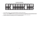
Specifications

10
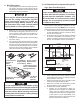
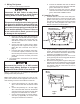
a. EVENLY tighten the bolts to a torque of
40 to 50 inch pounds. This will compress
the roof gasket to approximately 1/2". The
bolts are self locking so further tightening
is not necessary. See FIG. 13.
If bolts are left loose there may not be an ad-
equate roof seal or if over tightened, damage
may occur to the unit base or ceiling template.
Tighten to torque specications listed in this
manual.
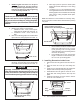
5. Installation of divider plate
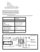
a. Measure the ceiling to roof thickness.
i. If distance is 2.0" - 3-3/4", remove perfo-
rated tab from divider plate. See FIG. 14.
ii. If distance is 3-3/4" - 5-1/2", remove no
tabs.
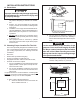
b. Remove the backing paper from double sided
tape located on ceiling template. See FIG. 14.
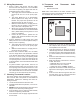
c. Place divider plate up to bottom of unit base
pan rmly. The foam tape on the divider plate
must seal to bottom of base pan. See FIG. 15.
Backing Paper
2.00" -3.75"
FIG. 14
d. With slight pressure push the divider plate
against the double sided tape on the ceiling
template.
e. Locate the 1/8" x 7" x 18" self adhesive insula-
tion supplied with the return air kit. Remove the
backing paper from the insulation and carefully
stick onto the ceiling template divider plate.
See FIG. 16.
Note: The adhesive on the insulation is extremely sticky.
Be sure the part is located where desired before pressing
into place.
Improper installation and sealing of divider
plate will cause the compressor to quick cycle
on the cold control. This may result in fuse or
circuit breaker opening and/or lack of cooling.
FIG. 15
Push Divider Plate Firmly
Onto Base Pan
i. Excess width is intended to seal the divider
plate to the sides of the 14-1/4" x 14-1/4"
(±1/8") opening. This is to help prevent
cold air discharge from circulating into the
unit return air opening.
ii. If the insulation is too high, stick excess
height of insulation to the unit base pan.
Do not cover up unit rating plate.
Place Insulation In Position
(Do Not Cover Unit Rating Plate)
Foam Tape
Divider Plate
FIG. 16
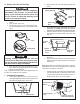
L. Installing Decorative Inside Cover
1. Remove the return air grill from the return air cov-
er.
2. Place the return air cover up to the ceiling tem-
plate.
3. Install cover to template with #8 x 3/8" blunt point
Phillips head screws provided (6 required).
4. Reinstall lter return air grill into return air cover.
Align tabs with mating notches and snap into
place.
5. Install two hole plugs into screw holes in back of
return air cover. See FIG. 17.
6. This completes the unit installation.
Return Air
Cover
Hole
Plugs
Return
Air Grill
FIG. 17